
APFC panels: sizing the steps, and avoiding resonance
How an automatic power factor panel decides what to switch, why the smallest step matters more than the total kVAr, and when you must fit detuned reactors.
An automatic power factor correction panel is a bank of capacitors, a set of contactors, and a controller that decides how many to switch in. The concept is simple enough that it gets specified by total kVAr and nothing else — and that is how plants end up with a correctly sized bank that never reaches its target, or worse, one that makes the harmonic situation dramatically worse.
This is what actually needs deciding: the step arrangement, the switching device, and whether you need detuned reactors.
Why fixed compensation is not enough
A fixed capacitor bank supplies the same kVAr regardless of what the plant is doing. Size it for full production and it overcorrects badly at night, pushing the power factor leading — penalised on many tariffs, and a cause of voltage rise at light load. Size it for the night load and it does almost nothing during the day.
Fixed compensation is right in exactly one case: a base load that genuinely never goes away. A transformer's magnetising current, or a large motor that runs continuously, can be fixed-compensated at the load. Everything that varies needs switching.
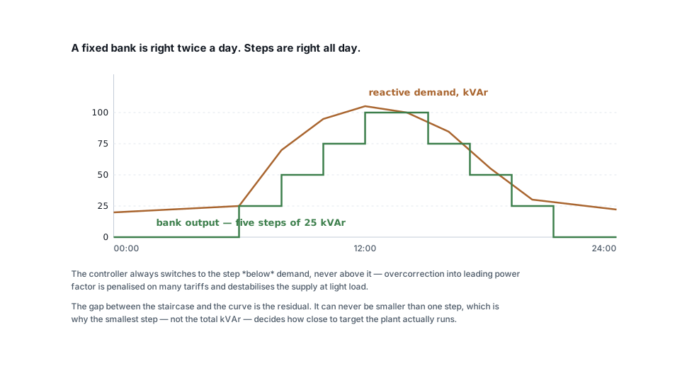
The smallest step decides your result
Everyone specifies the total kVAr. Work it out from your load and target with the power conversion calculator and it is straightforward. The number that decides whether you reach the target is the smallest step.
The controller can only switch whole steps, and it will only switch to a level at or below the reactive demand — going above means overcorrecting. So the residual reactive power is always somewhere between zero and one step. A 100 kVAr bank in one step is nearly useless; the same 100 kVAr in eight steps of 12.5 tracks the load closely all day.
Two common arrangements:
| Scheme | Example | Steps available | Notes |
|---|---|---|---|
| Equal | 8 × 12.5 kVAr | 12.5 kVAr resolution | Simple, even contactor wear, most common |
| Binary | 12.5 : 12.5 : 25 : 50 | 12.5 kVAr resolution from fewer contactors | Fewer devices, but the large steps switch often and wear unevenly |
Equal steps are the usual choice in India, and the controller can rotate which step it switches first to even out contactor wear. Binary schemes save contactors at the cost of switching the big ones more.
A practical starting point: make the smallest step about 5–10 % of the total bank, and never larger than the smallest meaningful load change on the plant.
The C/k setting, and the commissioning mistake
Every APFC controller needs to know how much current one step represents, seen through the incomer CT. That is the C/k setting:
C/k = (step kVAr × 1000) / (√3 × line voltage × CT ratio)
Set it too high and the controller cannot see the effect of its own smallest step, so it hunts — switching in and out repeatedly, wearing out contactors and capacitors. Set it too low and it becomes over-sensitive and does the same.
Hunting is the single most common APFC complaint, and it is almost always C/k, a CT on the wrong circuit, or a CT with reversed polarity. Before replacing anything, check that the CT sees all the load and the capacitors — a CT positioned so it does not see the capacitor current cannot possibly control it.
Switching devices
Capacitor duty contactors are not ordinary contactors. Energising a capacitor draws a huge inrush — 30 to 200 times rated current for a few milliseconds — so capacitor duty contactors have early-make auxiliary contacts with damping resistors that pre-charge the capacitor before the main contacts close. Fitting an ordinary AC-3 contactor instead welds the contacts within months.
Thyristor switching replaces contactors where the load changes fast — spot welding, lifts, crushers, presses. A contactor-based panel needs a discharge delay of 30 to 60 seconds before a step can be re-energised; a thyristor module switches at the zero crossing in milliseconds, with no inrush and no wear. It costs several times more and needs cooling, and it is the right answer whenever the load changes faster than the bank can follow.
Harmonics: where APFC panels go badly wrong
This is the part that turns a saving into a failure.
Capacitors are a low impedance to high frequencies. Put a capacitor bank on a supply that also has inductance — every transformer is an inductance — and there is a frequency at which the two resonate. If a harmonic current the plant generates happens to sit near that frequency, the resonant circuit amplifies it.
Symptoms: capacitors running hot, fuses blowing for no visible reason, capacitors failing repeatedly, nuisance tripping, and a measured harmonic distortion that is worse after the correction was installed than before.
The cure is a detuned reactor in series with each capacitor step. The reactor shifts the resonant frequency below the lowest significant harmonic, so the combination is inductive at all harmonic frequencies and can no longer amplify anything.
| Detuning | Tuned near | Use when |
|---|---|---|
| 7 % | 189 Hz | The usual choice — VFDs, rectifiers, 5th harmonic dominant |
| 14 % | 134 Hz | Significant 3rd harmonic — heavy single-phase and LED load |
| None | — | Only where non-linear load is genuinely negligible |
A working rule: if non-linear load exceeds about 20 % of the plant, specify detuned reactors. In 2026 that describes most plants. Reactors add cost and they raise the voltage across the capacitors, so the capacitors must be rated for it — a 440 V capacitor in a 7 % detuned step on a 415 V system is normal, and fitting standard 415 V capacitors there will fail them.
If distortion is severe, correction is the wrong tool entirely and you need an active harmonic filter. Measure before you decide.
Things that make a panel last
- Discharge resistors on every capacitor, sized to bring the terminals below 50 V within a minute. Without them a switched-out capacitor stays charged and the next switching operation happens onto a live capacitor.
- Ventilation. Capacitor life halves for roughly every 7–10 °C above rated temperature. An APFC panel in a hot corner with no ventilation is a panel that will be rebuilt in three years.
- HRC fuses on each step, rated for capacitor duty.
- Annual capacitance check. Capacitors lose capacitance as they age. A step that has degraded 20 % is still switching, still drawing current, and no longer delivering what the controller thinks it is. Measuring each step annually is a ten-minute job that explains a drifting power factor.
A specification that will not embarrass you
- Total kVAr from the measured load and a target of 0.95–0.98, not unity.
- Smallest step at 5–10 % of the total.
- Capacitor duty contactors, or thyristor modules if the load cycles fast.
- 7 % detuned reactors unless you have measured the harmonics and can justify leaving them out.
- Capacitors rated for the voltage with the reactors fitted.
- Discharge resistors, HRC fuses, and forced ventilation.
- The controller CT on the incomer, seeing both load and capacitors, polarity verified at commissioning.
Work out the kVAr first with the power factor calculator, and read what the penalty actually costs if you still need to justify the spend — the demand-charge saving is usually larger than the penalty it removes.
Related articles
More on power factor & power quality.
 Power factor & power quality
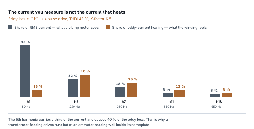
Transformer running hot: harmonics and K-factor
The ammeter reads 70 % of nameplate and the transformer is too hot to touch. Why eddy loss follows frequency squared, and what K-factor really tells you.
7 min read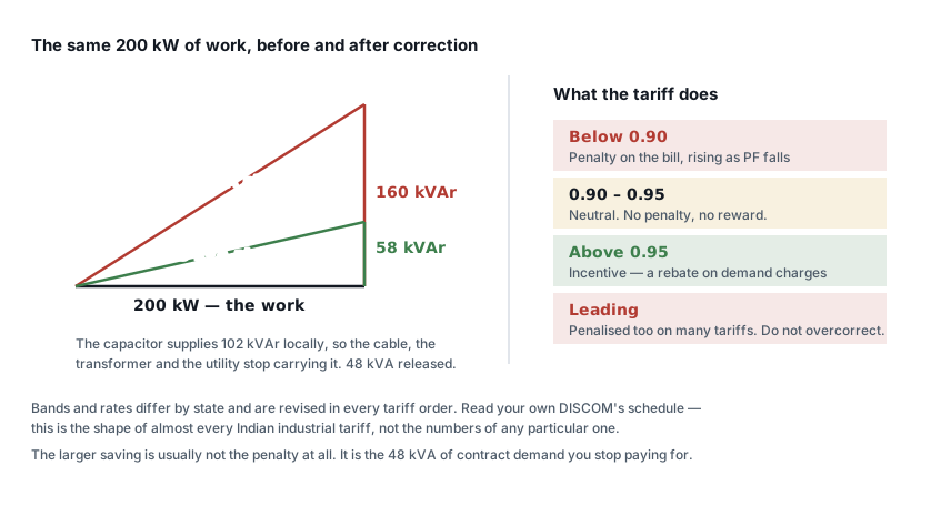 Power factor & power quality
The power factor penalty: what it costs, what fixing returns
Where reactive power comes from, how Indian tariffs charge for it, and a worked payback on a 200 kW plant — where the penalty is the smaller of the two savings.
6 min read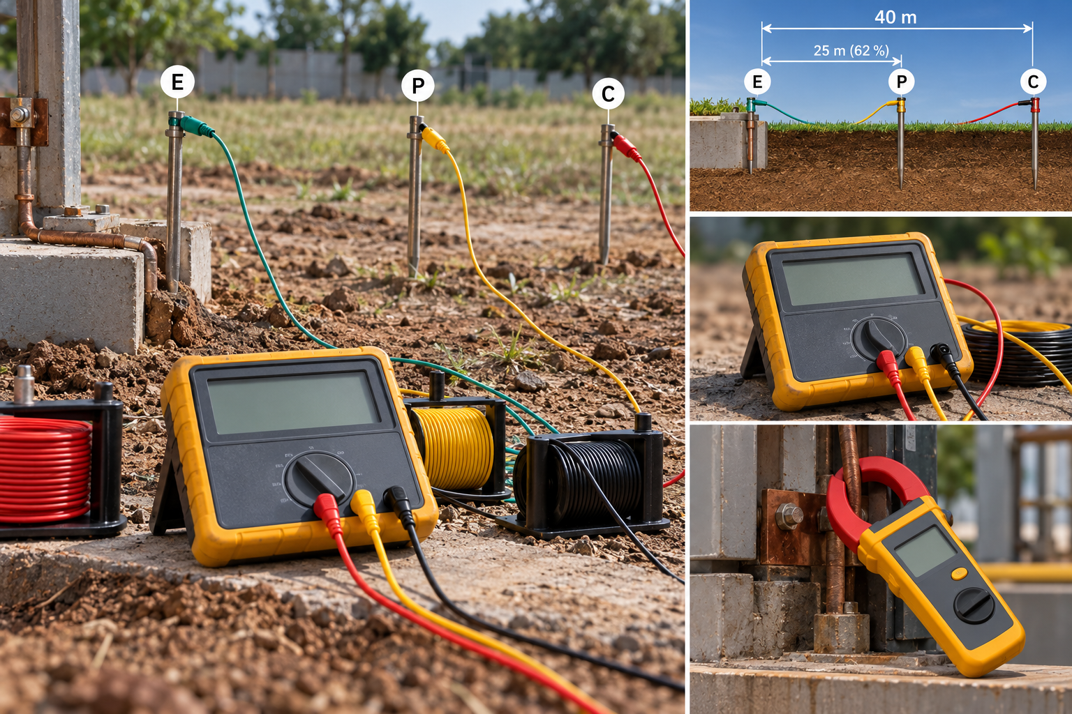 Panels, protection & earthing
Earth resistance testing: the 62 % rule, and when the clamp-on lies
Fall-of-potential done properly, the three-position check that proves it, IS 3043 limits by application, and when a clamp-on tester measures nothing.
8 min read Cable sizing
Cable size for large loads: when to run cables in parallel
Above 300 mm², a bigger cable size stops paying. When to run cables in parallel, the six rules for equal sharing, and the overload no breaker can see.
10 min read
Comments
Loading…