
Earth resistance testing: the 62 % rule, and when the clamp-on lies
Fall-of-potential done properly, the three-position check that proves it, IS 3043 limits by application, and when a clamp-on tester measures nothing.
A number written on a commissioning sheet next to the words "earth pit" is one of the most casually produced figures in the whole handover file. Someone walks out with a four-terminal tester, pushes two spikes into whatever ground is soft, presses the button, and writes down what appears.
Roughly half the time that number is wrong, and it is wrong in the dangerous direction: too low. A pit that reads 3.2 Ω because the spikes were badly placed will still read 3.2 Ω on the day it fails to clear a fault.
This is how the measurement actually works, where it goes wrong, and when the
clamp-on meter in your bag is telling you nothing at all.
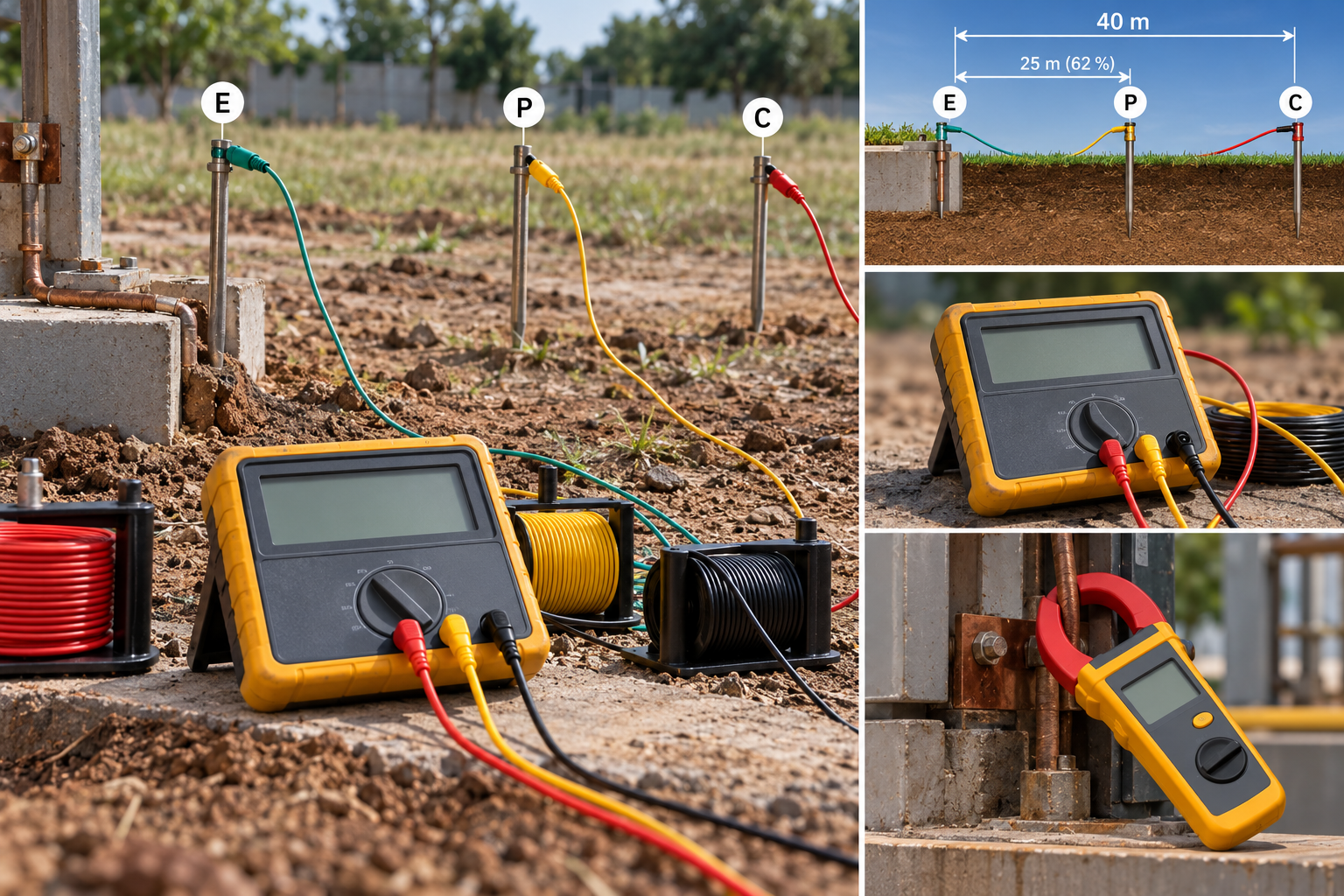
The three-point fall-of-potential method
Every reliable earth resistance measurement is a variation on one idea. Push a known current into the earth through the electrode under test, take it back through a remote current spike, and measure the voltage that develops along the way with a third spike in between. Ohm's law does the rest.
- E is the electrode under test, disconnected from the installation.
- C is the current spike, driven 30 to 50 m away in a straight line.
- P is the potential spike, between them.
The current flowing from E spreads into the soil, and the resistance you are trying to measure lives almost entirely in the first metre or two around the electrode, where the current density is highest. Get far enough away and the soil contributes nothing more. That is the whole basis of the method: you need P to sit in the flat region between two rising curves, out of E's influence and out of C's.
The 62 % rule puts it there. With C at 40 m, P goes at roughly 25 m. It is not arbitrary — for a uniform soil and a small electrode, 62 % of the distance is where the potential gradient flattens.
The check that separates a measurement from a guess
The 62 % position assumes uniform soil, and soil is never uniform. So do not take one reading. Take three:
| Potential spike at | Typical reading |
|---|---|
| 52 % of the distance to C | 3.9 Ω |
| 62 % of the distance to C | 4.1 Ω |
| 72 % of the distance to C | 4.2 Ω |
If the three agree within a few per cent, the curve is flat where you measured and the middle figure is real. If they disagree — 2.1 Ω, 4.1 Ω, 7.8 Ω — then P was never out of anyone's influence, and the only fix is to move C further out and repeat. Not to average them.
That disagreement is the single most common reason a pit reads low. Placing C too close puts the resistance areas of E and C on top of each other, and the tester reports a fraction of the real value.
On a large earth grid at a substation, "far enough" can mean several hundred metres, because the resistance area scales with the size of the electrode system. A 40 m lead set will not measure a grid. It will produce a number.
What the reading has to be
IS 3043 works by application rather than by a single figure:
| Installation | Maximum earth resistance |
|---|---|
| Large power stations | 0.5 Ω |
| Major substations | 1.0 Ω |
| Small substations | 2.0 Ω |
| All other cases, including general industrial and domestic | 5.0 Ω |
Two practical notes that the table does not carry. First, these are ceilings, not targets — a system designed to land exactly on 5 Ω in February has no margin for the summer. Second, the figure that matters for an RCD-protected TT installation is not the IS 3043 ceiling at all but the loop impedance the device needs to operate, which for a 30 mA RCD is a far easier number to hit.
Season is not a detail
Soil resistivity follows moisture, and moisture follows the calendar. The same pit that reads 3 Ω in August can read 9 Ω in April. In much of India that is a factor of two to three between the end of the monsoon and the end of the dry season.
So: test in the dry season if you want the number that matters, and if you cannot, write the date and the recent weather on the sheet. A pit commissioned at 4.6 Ω in September has not been shown to comply. It has been shown to comply in September.
Chemical and backfilled electrodes narrow that swing, which is most of what you are paying for. They do not remove it.
When the clamp-on meter works, and when it lies
A clamp-on earth tester induces a voltage into the earth conductor and measures the resulting current, giving you the resistance of the complete loop. It is fast, it needs no spikes, and it can be used without disconnecting anything. All of which makes it very tempting and frequently wrong.
It works when the electrode under test has a parallel return path through other electrodes — a multi-electrode system, or a pit bonded into a grid, or a pole earth returning through the system neutral. The loop it measures is your electrode in series with the parallel combination of everything else. When the "everything else" is large and low, that combination approaches zero and the reading approaches your electrode alone.
It fails completely on a single isolated electrode. There is no return path, so there is no loop, and the instrument will either refuse or report something meaningless. A standalone pit at a remote pump house cannot be clamp-tested. Nor can a newly installed pit before it is bonded in.
The failure is quiet. That is what makes it worth knowing.
Use the clamp-on for routine checks on a known-good multi-electrode system, where you are looking for the pit that has drifted rather than establishing a value for the first time. Use fall-of-potential for commissioning, for anything you are certifying, and for any pit that has just been dug.
Disconnect, or measure something else
The three-point method needs the electrode isolated from the installation. Leave it bonded and you are measuring your electrode in parallel with every other earth path on the site — water mains, cable armour, structural steel, the supply neutral. The result is genuinely low, genuinely reproducible, and genuinely not the resistance of your pit.
This is why every earth pit should have a disconnecting link in an accessible chamber, why it matters just as much for a lightning protection earth, and why a pit cast into a slab with the conductor buried is an asset nobody will ever test properly.
Safety, and this is not a formality. The moment you lift that link, the electrode may be the only thing standing between a fault and a person. Lift it for as short a time as possible, do not lift it during a thunderstorm, and treat the disconnected conductor as live — a working earth carries current, and on a system with a standing imbalance it can carry a lot.
Worked example
For the conductor that connects the pit to the system, the earthing conductor sizing calculator does the fault-current and duration arithmetic.
A 4 m driven rod at a packaged substation, tested in March.
- C spike at 40 m, in a straight line clear of buried services.
- P at 20.8 m (52 %), 24.8 m (62 %), 28.8 m (72 %).
- Readings: 2.6 Ω, 2.7 Ω, 2.9 Ω.
The spread is about 10 %, which is acceptable for a single rod. The value is 2.7 Ω, against a 2 Ω ceiling for a small substation.
It fails. And it fails in March, which is close to the worst case, so a second rod bonded in parallel and spaced at least its own length away will comfortably take it under. Two 4 m rods at 4 m spacing do not give you half the resistance — mutual interference means you get roughly 60 % of the single value, not 50 % — so expect around 1.6 Ω and retest rather than assuming.
Frequently asked questions
What is an acceptable earth pit resistance in India? IS 3043 sets 5 Ω for general industrial and domestic installations, 2 Ω for small substations, 1 Ω for major substations and 0.5 Ω for large power stations. These are maxima, and they should be met in the dry season.
Why does my earth resistance change between seasons? Because soil resistivity tracks moisture content. A two- to three-fold rise between the end of the monsoon and the end of summer is normal, so a pit commissioned just after rain may not comply eight months later.
Can I test an earth pit without disconnecting it? Only with a clamp-on tester, and only where the pit is part of a bonded multi-electrode system that provides a return path. For a commissioning value on a single electrode, the link must be lifted and the fall-of-potential method used.
How far apart should the test spikes be? Far enough that the resistance areas of the electrode and the current spike do not overlap. For a single rod, 30 to 50 m to the current spike is usually enough. For a substation grid it can be several hundred metres. The 52/62/72 % check tells you whether you went far enough.
Why do three readings at different spike positions matter? They prove the potential spike was in the flat part of the curve. Three readings that agree confirm the measurement. Three that scatter mean the current spike is too close, and the low reading you would have recorded is optimistic.
Standards referenced
- IS 3043 — Code of Practice for Earthing. Bureau of Indian Standards
Titles are given as commonly published. Check the current edition with the publisher before relying on a clause in professional work.
Related articles
More on panels, protection & earthing.
 Panels, protection & earthing
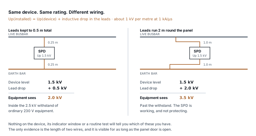
SPD installation: the two wires that decide
An SPD with 2 m of lead passes more than twice the voltage it should. Lead length, Uc and type selection, and how to check a panel you did not build.
7 min read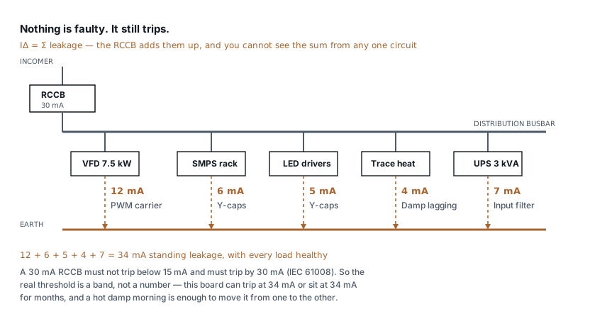 Panels, protection & earthing
RCCB keeps tripping: how to find the leakage
Healthy loads leak. Six of them on one board can trip a 30 mA RCCB with nothing faulty anywhere. How to measure the standing leakage and what to change.
8 min read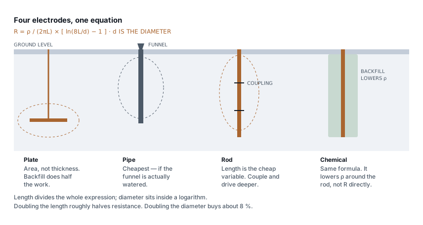 Panels, protection & earthing
Types of earthing: plate, pipe, rod and chemical compared
Plate, pipe, rod and chemical earthing all obey one formula. What separates them is soil resistivity, depth and who maintains them — not the electrode material.
7 min read Panels, protection & earthing
IP ratings for panels: what IP54, IP65 and IP66 survive
What each digit is tested against, why a higher rating derates your busbars, and the condensation problem that ruins sealed outdoor enclosures.
8 min read
Comments
Loading…