
Transformer running hot: harmonics and K-factor
The ammeter reads 70 % of nameplate and the transformer is too hot to touch. Why eddy loss follows frequency squared, and what K-factor really tells you.
A transformer that runs hot at an ammeter reading well inside its nameplate is one of the more disorienting things to find on a site visit. The load is 650 kVA on a 1000 kVA unit. The ventilation is clear. The taps are right. The oil or winding temperature says otherwise, and if you go by current alone there is nothing to explain it.
The current is not the problem. The shape of it is.
Heating follows the square of the frequency
A transformer has two kinds of load loss. The I²R loss in the winding resistance depends only on the RMS current, and it does not care what shape the waveform is. The eddy current loss — circulating currents induced in the conductors and the structural steel — rises with the square of frequency.
That second term is what harmonics do to a transformer. A 5th harmonic component is at 250 Hz, so for the same current magnitude it produces twenty-five times the eddy loss of the fundamental. The 7th produces forty-nine times.
Run the arithmetic on an ordinary six-pulse drive load and the result is counterintuitive:
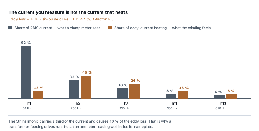
The fundamental carries 92 % of the current and causes 13 % of the eddy loss. The 5th carries a third of the current and causes 40 % of it. Your ammeter is dominated by the component that barely heats anything, and is nearly blind to the ones doing the damage.
This is the whole phenomenon. Everything below is bookkeeping on top of it.
What K-factor actually is
K-factor puts a single number on that spectrum. Under IEEE C57.110 it is:
K = Σ (Ih(pu)² × h²)
where Ih(pu) is each harmonic's current as a fraction of the total RMS
current, and h is the harmonic order. It is a weighted sum in which every
term is scaled by the square of its frequency — precisely the eddy loss
weighting above.
For the spectrum in the diagram — a typical 6-pulse drive at 42 % current distortion — K works out at about 6.5. A purely linear load is K = 1 by definition.
Two things about K-factor are worth being clear on, because both are commonly muddled:
K-factor is a property of the load, not the transformer. You calculate it from a measured current spectrum. A "K-13 transformer" is one built to tolerate a load of K up to 13 — larger conductors, transposed windings, oversized neutral, more core steel. Buying a K-rated transformer does not reduce your harmonics; it means the transformer survives them.
K-factor is not THD, and they do not convert. Two loads with the same THD can have very different K-factors depending on which harmonics carry the distortion, because of that h² weighting. THD tells you how distorted the waveform is. K tells you how much it will heat a transformer. Quoting one when you mean the other is the most common error in this area.
Derating: the honest version
The rule you will find repeated is "derate the transformer". The number attached to it varies wildly between sources, and most of them are guessing.
The real calculation in C57.110 needs one parameter you cannot infer from the nameplate: PEC-R, the winding eddy current loss as a fraction of I²R loss at rated current. It is typically a few percent for a distribution transformer and much higher for a large unit with heavy conductors. The derating for a given K depends strongly on it, which is why a 1000 kVA transformer might carry 750 kVA under one drive load and 850 kVA under the same K with a different construction.
So the practical position is:
- If you are specifying a new transformer for a known drive load, ask the manufacturer for the derating at your measured spectrum, or buy a K-rated unit and size normally. Both are answerable questions for them and guesswork for you.
- If you are assessing an existing one, stop calculating and measure the temperature. Winding or top-oil temperature against the rated rise is the direct answer, and it accounts for every effect at once — including the ones no formula on this page covers.
The THD and harmonic losses calculator will take a measured spectrum and give you the loss picture; the transformer sizing calculator covers the conventional side of the question.
Reading your own installation
Measure with the right instrument. An averaging clamp meter reads a distorted waveform low — sometimes 20 % low. You want true RMS, and for the spectrum itself a power quality analyser rather than a multimeter. If the only number you have is from an averaging meter, you do not yet know the load current, let alone its shape.
Measure at the transformer secondary, not at the drive. Harmonics from several loads do not simply add; some cancel, particularly between drives on different phases or with different DC bus loading. The spectrum that matters is the one arriving at the transformer.
Check the neutral. Triplen harmonics — 3rd, 9th, 15th — do not cancel in the neutral of a four-wire system; they add. A neutral running hotter than the phases, or carrying more current than any phase, is that, and it is a wiring capacity problem as well as a transformer one. Six-pulse drives are three-wire and produce little triplen content, but single-phase SMPS loads produce a great deal.
Look at the load mix before blaming the drives. A floor of LED drivers and SMPS supplies can produce a worse spectrum than one large VFD, and it does not announce itself the way a drive panel does.
The capacitor bank makes it worse, not better
If the site has power factor correction, harmonics stop being purely a heating problem and become a resonance problem.
A capacitor bank and the supply transformer's leakage inductance form a parallel resonant circuit at some frequency. If that frequency lands near a harmonic the load is producing — the 5th and 7th are the usual suspects — current at that harmonic circulates between the two and is amplified, not absorbed. Capacitors overheat and fail, fuses blow with no obvious fault, and the transformer gets hotter than the load alone explains.
Switching a capacitor step changes the resonant frequency, which is why this often looks like an intermittent fault correlated with nothing obvious. APFC panels: sizing the steps, and avoiding resonance covers how the steps interact and what detuned reactors are for.
What to actually do
In rough order of cost:
- Move loads between transformers so the drive load is not concentrated on one unit. Free, if you have the spare capacity.
- Detune the capacitor bank with series reactors, usually at 7 % or 14 %, which shifts the resonance below the 5th harmonic. This is the standard fix and is often the whole answer on sites where PFC is present.
- Fit line reactors or DC link chokes on the drives. A 3 % line reactor typically takes a 6-pulse drive's THDi from about 80 % down to 35–40 %. This is the cheapest real harmonic reduction available and is often omitted to save money at panel build.
- Passive or active filters, when the above is not enough.
- 12-pulse or active front-end drives for new large installations, which cancel the 5th and 7th at source.
- A K-rated transformer, which does not reduce harmonics but stops them shortening the transformer's life.
What this does not cover
This is about heating in the transformer. Harmonics also cause motor heating and torque pulsation, nuisance tripping of protective devices, and metering error — that last one matters commercially, since a distorted waveform can put your meter and the utility's meter in disagreement.
It also does not address the utility's limits on what you may inject. IEEE 519 sets injection limits at the point of common coupling based on your demand relative to the supply's short circuit capacity, and an installation can be comfortable internally while being outside those limits.
And it assumes the heat is harmonics. It might not be. Overloading, a blocked radiator, a failing fan, high ambient, a loose connection or degraded oil all produce a hot transformer too, and several of them progress faster than harmonic heating does. Why distribution transformers fail covers the other routes — worth reading first if the temperature rose suddenly rather than creeping up over months as load was added.
Standards referenced
- IEEE 519 — Recommended Practice and Requirements for Harmonic Control in Electric Power Systems. IEEE
Titles are given as commonly published. Check the current edition with the publisher before relying on a clause in professional work.
Related articles
More on power factor & power quality.
 Power factor & power quality
APFC panels: sizing the steps, and avoiding resonance
How an automatic power factor panel decides what to switch, why the smallest step matters more than the total kVAr, and when you must fit detuned reactors.
6 min read Power factor & power quality
The power factor penalty: what it costs, what fixing returns
Where reactive power comes from, how Indian tariffs charge for it, and a worked payback on a 200 kW plant — where the penalty is the smaller of the two savings.
6 min read Panels, protection & earthing
Earth resistance testing: the 62 % rule, and when the clamp-on lies
Fall-of-potential done properly, the three-position check that proves it, IS 3043 limits by application, and when a clamp-on tester measures nothing.
8 min read Cable sizing
Cable size for large loads: when to run cables in parallel
Above 300 mm², a bigger cable size stops paying. When to run cables in parallel, the six rules for equal sharing, and the overload no breaker can see.
10 min read
Comments
Loading…