
RCCB keeps tripping: how to find the leakage
Healthy loads leak. Six of them on one board can trip a 30 mA RCCB with nothing faulty anywhere. How to measure the standing leakage and what to change.
An MCCB that trips is telling you something drew too much current. An RCCB that trips is telling you something quite different: that the current going out did not all come back. Those are not the same problem, and the second one is routinely misdiagnosed — usually by fitting a less sensitive device, which is the one response that makes the installation more dangerous rather than less.
Before anything else, establish which kind of trip you have. Does it trip at a moment, or at random? A trip that lands every time a specific motor starts, or every time the pump cuts in, points at one circuit and one event. A trip that happens at 6 a.m. on damp mornings and never at 3 p.m. points at something cumulative. The two need different work, and the rest of this follows that split.
The threshold is a band, not a number
The first thing worth knowing is that a 30 mA RCCB does not trip at 30 mA.
Under IEC 61008, a residual current device must not operate below 0.5 IΔn, and must operate by IΔn. For a 30 mA device that means anywhere between 15 mA and 30 mA is compliant behaviour. Two identical devices from the same box can sit either side of each other, and the same device drifts a little with temperature and age.
This matters more than it sounds. An installation running at 20 mA of standing leakage is not "within limits with 10 mA to spare". It is inside the band where a compliant device is permitted to trip, and whether it does is a matter of which unit you happened to fit. That is why a board can run for eight months and then start tripping after nothing changed except the weather.
Where the milliamps come from
Almost every modern load leaks a little to earth by design. Switch-mode power supplies have Y-capacitors from line and neutral to the chassis to meet EMC limits — those capacitors conduct a small standing current to earth whenever the supply is live. It is not a fault. It is the filter doing its job.
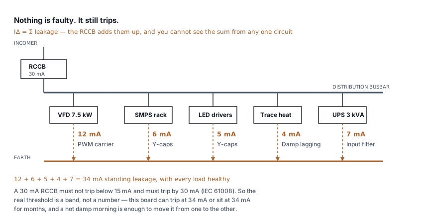
The trap is that leakage is per load and cumulative per device. You can megger every circuit individually, find every one healthy, and still have a board that trips — because nothing you measured one circuit at a time shows you the sum the RCCB sees.
Typical standing figures, for orientation rather than design:
| Load | Standing leakage, roughly |
|---|---|
| Desktop PC or small SMPS | 0.5–1 mA |
| 19-inch rack of SMPS supplies | 5–10 mA |
| LED driver bank | 3–8 mA |
| VFD, 7.5 kW, short screened cable | 5–15 mA |
| VFD, 7.5 kW, 40 m screened cable | 15–30 mA |
| Trace heating, damp lagging | 2–10 mA |
Five ordinary loads reach 34 mA with nothing wrong. That is the single most common cause of "the RCCB trips and I cannot find the fault", and no amount of insulation testing will find it, because there is no fault to find.
A VFD is a device-type problem, not a rating problem
Drives deserve their own paragraph because they break RCCBs in a way that looks like a fault and is not.
A VFD rectifies the incoming supply to a DC bus and switches it at several kilohertz. Cable capacitance couples that switching edge to earth, so the leakage from a drive is not a small sinusoidal current — it is a high-frequency current with a DC component, and it scales with motor cable length and switching frequency.
That matters because RCCBs come in types, and the type describes what the device can detect:
| Type | Detects | Use |
|---|---|---|
| AC | Sinusoidal AC residual current only | Resistive and simple loads |
| A | AC plus pulsating DC | Most electronic loads, SMPS |
| F | Type A plus mixed frequencies | Single-phase drives |
| B | Type A plus smooth DC and high frequency | Three-phase VFDs, PV inverters |
A Type AC device on a drive circuit is not merely prone to nuisance tripping. Smooth DC leakage can magnetically saturate the core of a Type AC device, at which point it stops detecting residual current at all — including a real earth fault. The device looks fine, tests fine with a press of the test button, and has stopped protecting anybody. Test buttons check the mechanism, not the core.
If there is a three-phase drive downstream, it wants Type B. This is a selection error far more often than it is a fault.
Do not fix it by fitting a bigger one
The reflex, when a 30 mA device keeps tripping, is to fit a 100 mA or 300 mA one. The tripping stops. So does the protection.
The ratings are not a nuisance scale — they are different jobs:
- 30 mA is personnel protection. It is chosen because it sits below the threshold at which mains-frequency current through the chest causes ventricular fibrillation, for a shock duration a device of that sensitivity can clear. It is the only rating that does that job.
- 100 mA and 300 mA are fire protection. They limit sustained earth leakage into building fabric. They will not save anyone touching a live part.
Swapping the first for the second because the board is inconvenient converts a safety device into a device that reports nothing until the leakage is ten times worse. In Indian installations 30 mA protection is required on socket circuits and wet areas, and removing it is a non-conformity that also happens to be the kind of thing that gets found after an incident rather than before.
The correct arrangement, when you genuinely need a less sensitive device upstream, is selectivity, not desensitising: a 300 mA Type S (time delayed) device at the incomer with 30 mA instantaneous devices on the final circuits. The upstream device is slower as well as less sensitive, so a downstream fault clears at the downstream device and the board stays up. Fitting two instantaneous devices in series achieves nothing — both see the same current and whichever is quicker wins, usually the wrong one.
Finding it: a sequence that works
The whole problem is that you cannot see the sum. So measure it.
1. Measure the standing leakage with everything on. A clamp meter with a leakage range (milliamp resolution, not a normal current clamp) around all live conductors together — three phases and neutral, not the earth conductor — reads the residual current directly. That single number tells you whether you are chasing a fault or a design problem. Above about half the device rating with no fault present, it is cumulative leakage and no fault exists to find.
2. Split the board. Switch off every outgoing way, confirm the leakage falls to near zero, then switch them back on one at a time and record the number after each. You get a per-circuit contribution in about ten minutes, and the offenders are usually obvious: one drive contributing more than the other seven circuits combined.
3. Only now reach for the insulation tester. If one circuit contributes far more than its load justifies, megger that circuit — disconnected, at 500 V, against earth. Below 1 MΩ on an LT circuit, you have a real insulation problem and the tripping is the system working correctly. Above about 10 MΩ, the insulation is fine and the leakage is the equipment's own filtering.
4. Check the neutral–earth connection. A neutral bonded to earth downstream of the device — a common wiring error when a sub-board is added — provides a parallel return path and produces an imbalance that looks exactly like leakage. It trips at odd loads and defeats every other test. Disconnect the outgoing neutral and megger it to earth; anything but open circuit downstream of the device is wrong.
What to actually change
Once you know the number and the contributors, the options are ordinary engineering rather than guesswork:
- Split the load across more devices. Two 30 mA devices with 17 mA each is compliant, safe and stops tripping. This is the fix in most cumulative cases.
- Fit the right type. Type B where drives are involved, Type A as a general minimum for anything electronic.
- Shorten motor cables, or lower the drive's switching frequency. Both reduce drive leakage directly, and the second is a parameter change.
- Fix the damp. Trace heating and outdoor panels that leak in the monsoon and not in April are telling you about water ingress, and the leakage is the symptom rather than the problem.
What this does not cover
This is about finding standing leakage and choosing the right device. It does not tell you whether your earthing is adequate to make that device work: an RCCB needs a low-impedance earth return to clear a fault in time, and a device in front of a 40 Ω electrode is protection on paper. That is a separate check, and earthing design under IS 3043 covers what the electrode has to achieve. The earthing conductor calculator will size the conductor once you know the fault level.
Nor does it cover arc fault detection, which is a different device answering a different question, or the discrimination study a large installation needs rather than the rule of thumb above.
And it assumes the device itself is sound. An RCCB is a mechanism with a spring, and they do fail — usually by failing to trip rather than by tripping early. Press the test button quarterly. It proves the mechanism moves, which is the one thing none of the measurements above tell you.
Standards referenced
- IS 3043 — Code of Practice for Earthing. Bureau of Indian Standards
Titles are given as commonly published. Check the current edition with the publisher before relying on a clause in professional work.
Related articles
More on panels, protection & earthing.
 Panels, protection & earthing
Earth resistance testing: the 62 % rule, and when the clamp-on lies
Fall-of-potential done properly, the three-position check that proves it, IS 3043 limits by application, and when a clamp-on tester measures nothing.
8 min read Panels, protection & earthing
SPD installation: the two wires that decide
An SPD with 2 m of lead passes more than twice the voltage it should. Lead length, Uc and type selection, and how to check a panel you did not build.
7 min read Panels, protection & earthing
Types of earthing: plate, pipe, rod and chemical compared
Plate, pipe, rod and chemical earthing all obey one formula. What separates them is soil resistivity, depth and who maintains them — not the electrode material.
7 min read Panels, protection & earthing
IP ratings for panels: what IP54, IP65 and IP66 survive
What each digit is tested against, why a higher rating derates your busbars, and the condensation problem that ruins sealed outdoor enclosures.
8 min read
Comments
Loading…