
SPD installation: the two wires that decide
An SPD with 2 m of lead passes more than twice the voltage it should. Lead length, Uc and type selection, and how to check a panel you did not build.
A surge protection device is the only item in a panel that can be correctly specified, correctly purchased, correctly installed to the letter of the wiring diagram, show a green indicator for ten years — and protect nothing at all.
It is not a subtle failure. A device with two metres of connecting lead passes roughly twice the voltage to the equipment behind it as the same device with half a metre. Nothing on the device says so. The indicator window reports whether the varistor is still alive, not whether the installation works. And unlike an RCCB, there is no test button that fails.
The whole thing turns on two wires and one number.
Two wires decide whether it works
An SPD does not block a surge. It clamps: when the voltage across it exceeds a threshold, it becomes a low-impedance path and diverts the surge current to earth. What the protected equipment actually experiences is the let-through voltage, and that is the sum of two things:
The device's own protection level, Up. Printed on the label, typically 1.2–1.5 kV for a Type 2 device on a 230/400 V system. This is the number people compare when buying.
The inductive drop in the connecting leads. This is the number nobody compares, and it is usually larger.
A surge is not a slow event. A standard 8/20 µs test waveform rises at
something like 1 kA/µs, and the voltage a conductor develops under a changing
current is V = L × di/dt. Ordinary panel wiring has roughly 1 µH per metre.
At 1 kA/µs, one metre of lead contributes about 1 kV — and there are two
leads, the one to the busbar and the one to the earth bar, so what counts is
the total loop length.
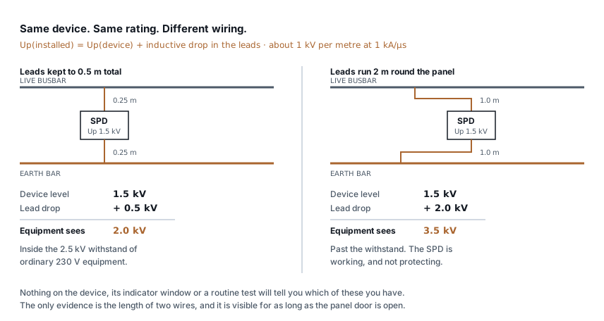
The rule that follows is the one thing to remember from this page: keep the total lead length, busbar to SPD and SPD back to earth bar, under 0.5 metres. Every standard that addresses it says the same, and it is the single most violated requirement in Indian LT panels — because a metre of extra cable costs nothing, looks tidier, and makes the device measurably worse.
For context on why 2.5 kV keeps appearing below: ordinary 230 V equipment in a building installation is built to an impulse withstand category that assumes about 2.5 kV at the socket. A 2.0 kV let-through sits inside that. A 3.5 kV let-through does not, which means the surge reaches the load with the SPD conducting exactly as designed.
Uc is the other half, and gets it wrong more often
The second number is Uc, the maximum continuous operating voltage — the voltage the device can sit across indefinitely without conducting.
Undersize it and the device does not fail in a surge. It fails on an ordinary Tuesday, because Indian LT supplies do not sit politely at 230 V. Phase voltage excursions to 260 V are routine, and a lost neutral on a three-phase supply puts single-phase loads across a much higher voltage for as long as it takes somebody to notice.
A device chosen with Uc = 275 V on a supply that regularly touches 260 V is running with very little margin. It heats, the varistor degrades, and it either opens its thermal disconnector — leaving you unprotected with a green light still showing on the other pole — or it fails short and takes out its backup device.
| System | Practical Uc |
|---|---|
| TN-S, stable urban supply | 275 V |
| TN-S, supply with regular excursions | 320 V |
| TT system, line to neutral | 320 V or higher |
Higher Uc costs a little more let-through voltage, so it is a trade rather than a free upgrade. But a device that has quietly disconnected itself protects nothing at any Up.
Type 1, Type 2, Type 3 — and why one is not enough
The types are not quality grades. They describe what the device is built to survive, and they belong at different points in the installation.
| Type | Tested with | Where | Typical rating |
|---|---|---|---|
| Type 1 | 10/350 µs impulse | Main incomer, where a lightning protection system or overhead line can inject direct strike current | Iimp ≥ 12.5 kA |
| Type 2 | 8/20 µs impulse | Sub-distribution boards | In ≥ 20 kA |
| Type 3 | Combination wave | At sensitive equipment, close-coupled | In ≥ 5 kA |
The 10/350 µs waveform carries far more energy than 8/20 µs at the same peak, which is why a Type 2 device at an incomer exposed to direct strike current does not merely fail — it fails energetically.
Type 3 devices are the ones most often skipped, and they are the reason a "protected" installation still loses a PLC. The Type 2 device at the board brings the surge down to around 1.5 kV. Sensitive electronics can want 1 kV or less, and the cable run from board to equipment picks up its own induced voltage. Coordination between stages is the design, not any single device.
Checking a panel you did not build
Five things, in order, and the first three need nothing but the door open:
1. Measure the leads. Busbar to SPD, SPD to earth bar. Add them. If the total is over half a metre, that is your finding, and it usually costs one short length of cable to fix. Straighten any loops while you are there — a coiled "spare" length of earth lead is an inductor, deliberately wound.
2. Look at where the earth lead goes. It wants the earth bar directly, by the shortest route. Not a daisy chain through three other terminals, not a twist-on connector, not a lug shared with something else. Every joint is resistance and every detour is length.
3. Read the indicator, and do not trust it. A green window means the varistor has not yet failed. It says nothing about lead length, Uc margin, or whether the backup device upstream is the right size. It is the least informative healthy-looking thing in the panel.
4. Check the backup protection. An SPD needs an upstream device sized to its datasheet — usually a specific gG fuse rating. Too small and it opens on the first real surge, removing protection permanently and silently. Too large and a failing SPD is not disconnected.
5. Check what it is bonded to. An SPD diverts surge current to earth, so its performance is capped by the earth it diverts into. A device wired to an electrode of 30 Ω is a device whose earth is the limiting element, and earthing design under IS 3043 covers what the electrode has to achieve. The earthing conductor calculator sizes the conductor once you know the fault level.
Getting it right on a new panel
Put the SPD physically adjacent to the incoming terminals and the earth bar at design stage. This is a layout decision, not a wiring decision, and it is almost free before the panel is built and awkward afterwards.
Use the V-connection (Kelvin, or cascaded) arrangement where the device allows it, so the incoming and outgoing conductors land on the SPD terminals themselves rather than the device hanging off a tee. That removes the lead inductance from the protected path entirely rather than shortening it.
Specify Uc for the supply you actually have, not the one on the drawing. And size the earth conductor for the surge current, not just for continuity — this is a conductor that has to carry kiloamps for microseconds.
What this does not cover
This is about the LT side of a distribution board. It is not a lightning protection design: the air terminations, down conductors and separation distances of a structural LPS are a different discipline and a different standard, and an SPD is what happens after that system does its job, not a substitute for it.
It also assumes a single board. A large installation needs coordination between Type 1, 2 and 3 stages with proper separation distance between them — put a Type 2 device ten centimetres from a Type 1 and the two do not share the current the way the datasheet assumes.
And nothing here tells you whether a surge is what killed the equipment you are holding. Surge damage and heat damage look similar after the fact, and if the answer matters commercially, it wants a laboratory rather than a panel inspection.
Standards referenced
- IS 3043 — Code of Practice for Earthing. Bureau of Indian Standards
Titles are given as commonly published. Check the current edition with the publisher before relying on a clause in professional work.
Related articles
More on panels, protection & earthing.
 Panels, protection & earthing
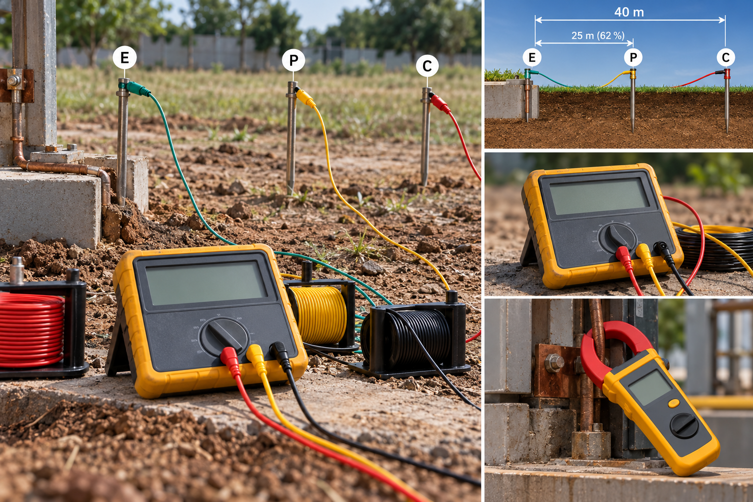
Earth resistance testing: the 62 % rule, and when the clamp-on lies
Fall-of-potential done properly, the three-position check that proves it, IS 3043 limits by application, and when a clamp-on tester measures nothing.
8 min read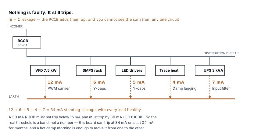 Panels, protection & earthing
RCCB keeps tripping: how to find the leakage
Healthy loads leak. Six of them on one board can trip a 30 mA RCCB with nothing faulty anywhere. How to measure the standing leakage and what to change.
8 min read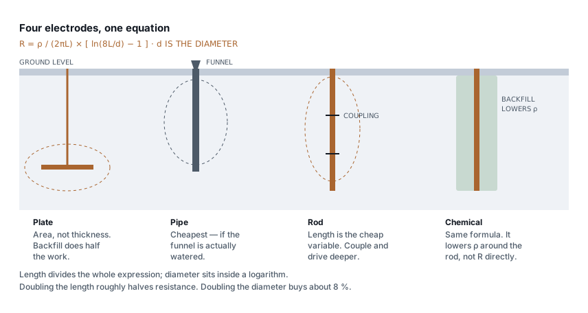 Panels, protection & earthing
Types of earthing: plate, pipe, rod and chemical compared
Plate, pipe, rod and chemical earthing all obey one formula. What separates them is soil resistivity, depth and who maintains them — not the electrode material.
7 min read Panels, protection & earthing
IP ratings for panels: what IP54, IP65 and IP66 survive
What each digit is tested against, why a higher rating derates your busbars, and the condensation problem that ruins sealed outdoor enclosures.
8 min read
Comments
Loading…