
Earthing design under IS 3043: electrodes, soil and pits
Soil resistivity, how many earth pits you need, why doubling the rods does not halve the resistance, and the separate-earths myth that destroys equipment.
Earthing is the part of an installation most often built to a rule of thumb — "two pits for the body, one for the neutral" — and least often measured. The rule of thumb produces a number nobody checks, on soil nobody tested, connected by a conductor nobody sized.
This is what IS 3043 actually asks for: what an earth electrode does, how soil decides the answer, and why the number of pits is the last thing to decide rather than the first.
Two different jobs, often confused
System earthing connects the supply neutral to earth. It fixes the voltage of the system relative to ground and gives earth fault current a defined path back to the source. It is the transformer's neutral earth.
Equipment earthing connects the metal parts of equipment together and back to that same point, so a fault to an enclosure becomes a large current that trips a device rather than a lethal voltage waiting for somebody's hand.
They are different jobs and the standard treats them separately — but they must end up bonded together, for the reason in the last section of this post.
Start with the soil, not the pits
The resistance of an earth electrode is dominated by the soil immediately around it. Soil resistivity varies over two orders of magnitude:
| Soil | Resistivity, Ω·m |
|---|---|
| Marshy, saline | 5 – 30 |
| Clay, loam, damp | 30 – 100 |
| Mixed sandy clay | 100 – 200 |
| Dry sand | 300 – 1,000 |
| Rock, laterite, gravel | 1,000 – 10,000 |
Measure it with the Wenner four-pin method before designing anything. Four
electrodes in a line at equal spacing a, inject current through the outer
pair, measure voltage across the inner pair, and ρ = 2πaR. Repeat at several
spacings — the spacing roughly corresponds to the depth being sampled, so
increasing it tells you whether there is better soil deeper down. That single
afternoon replaces every guess in the design.
The resistance of one electrode
For a single driven rod:
R = ρ / (2πL) × [ln(8L/d) − 1]
with ρ the soil resistivity in Ω·m, L the buried length and d the diameter,
both in metres.
A 3 m rod of 40 mm pipe in 100 Ω·m soil:
R = 100 / (2π × 3) × [ln(600) − 1]
  = 5.31 × (6.40 − 1)
  = 28.6 Ω
One rod, in perfectly reasonable soil, is 28.6 Ω. If your target is 5 Ω, one pit was never going to do it, and no amount of salt in the backfill changes that by a factor of six.
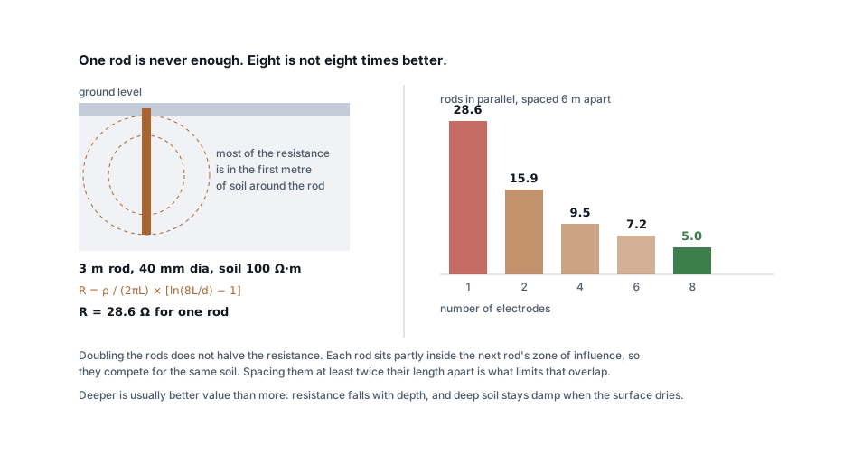
Note what the formula says about depth: R falls roughly with 1/L, and the
ln term adds a little more. Doubling the rod length does more than adding a
second rod — and deep soil holds moisture when the top metre dries out in
summer, which is when your earth resistance would otherwise be at its worst.
Why more pits give less than you expect
Put two rods in parallel and you do not get half the resistance. Each rod sits partly inside the other's zone of influence, so they compete for the same soil.
| Rods | Resistance from 28.6 Ω each |
|---|---|
| 1 | 28.6 Ω |
| 2 | 15.9 Ω |
| 4 | 9.5 Ω |
| 6 | 7.2 Ω |
| 8 | 5.0 Ω |
Space them at least twice their length apart — 6 m for a 3 m rod — and the overlap is limited. Space them 1 m apart, as often happens where there is no room, and the group behaves almost like a single electrode no matter how many you drive.
Target resistances
Common Indian practice, and the figures IS 3043 works towards:
| Installation | Target |
|---|---|
| Large substation, HT | ≤ 1 Ω |
| LT industrial and commercial | ≤ 5 Ω |
| Lightning protection | ≤ 2 Ω, per IS/IEC 62305 |
| Sensitive electronics, medical | ≤ 1 Ω |
Two cautions. A low number measured in February means nothing if it triples in May — measure in the dry season, or apply a seasonal factor. And resistance is not the safety criterion; touch and step voltage are. A low resistance helps, but on a large installation what matters is that everything a person can touch is at the same potential.
Electrodes and backfill
| Type | Notes |
|---|---|
| GI pipe, 40 mm × 3 m | The traditional Indian pit. Cheap, corrodes, needs maintenance |
| Copper-bonded rod, 14–17 mm | Coupled and driven deep. Better life, better value per ohm |
| Plate, 600 × 600 GI or copper | Where rock prevents driving. Poor resistance per rupee |
| Chemical / maintenance-free | Backfilled with a hygroscopic compound, sealed. Good in poor soil |
| Strip / horizontal conductor | Trenched, often the best option in shallow soil over rock |
Backfill matters as much as the electrode. Bentonite retains moisture and lowers contact resistance. Charcoal and salt is the traditional mix and it works — but salt leaches away within a few years and accelerates corrosion of the electrode, so it is a treatment that needs repeating and shortens the pit's life. Watering pits is not a design, it is a maintenance dependency.
Whatever you install, the connection between electrode and conductor must be accessible for testing and inspection — that is what the chamber and the removable link are for, and it is the first thing to be concreted over on a busy site.
Size the conductor, not just the pit
The earth conductor has to carry the fault current for as long as the protective device takes to clear it. That is a calculation, not a convention:
S = √(I² t) / k
The earthing conductor calculator runs it against both the adiabatic result and the table method and returns the larger. IS 3043 also sets minimum sizes for mechanical and corrosion reasons regardless of the arithmetic — 16 mm² for buried bare copper, 25 mm² for aluminium — because a conductor thin enough to corrode through will do exactly that, unnoticed, until the day it is needed.
The separate-earths myth
The most damaging idea in Indian earthing practice is that sensitive equipment deserves its own "clean" earth, isolated from the "dirty" power earth.
It does not, and the reason is voltage. Two earth systems at different points in the soil sit at different potentials during a fault or a lightning strike — potentially thousands of volts apart. A server with its chassis on one earth and its data cable referenced to the other is bridging that difference. The equipment becomes the connection between two earths, and it is destroyed doing it.
The correct approach is one earthing system, bonded together, with separate conductors run radially back to a common earth bar if noise is a concern. Star topology for the wiring, single point for the earth. IS 3043 and every international standard say the same thing, and the practice persists anyway because "separate earth" sounds like it should mean cleaner.
Testing, and what to record
- Fall-of-potential (three-pin) is the reference method. It requires disconnecting the electrode under test and adequate spacing for the auxiliary spikes.
- Clamp-on earth testers measure a loop rather than an electrode. Fast and useful for routine checks on a multi-electrode system, misleading on a single isolated electrode.
- Record the soil resistivity, the season, the electrode arrangement and the measured resistance — not just the final number. Without the first three, a future engineer cannot tell whether a rising reading means corrosion or just a dry month.
Retest annually. Earth resistance is one of the very few things in an installation that gets worse on its own.
Standards referenced
- IS 3043 — Code of Practice for Earthing. Bureau of Indian Standards
- IEC 62305 — Protection against lightning. International Electrotechnical Commission
Titles are given as commonly published. Check the current edition with the publisher before relying on a clause in professional work.
Related articles
More on panels, protection & earthing.
 Panels, protection & earthing
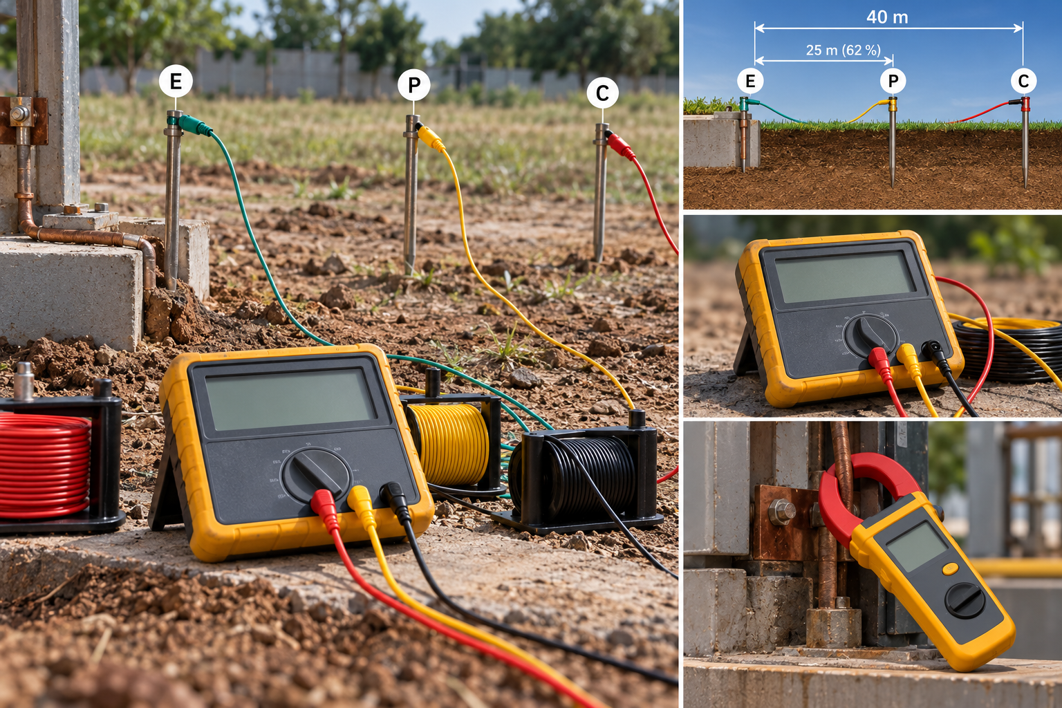
Earth resistance testing: the 62 % rule, and when the clamp-on lies
Fall-of-potential done properly, the three-position check that proves it, IS 3043 limits by application, and when a clamp-on tester measures nothing.
8 min read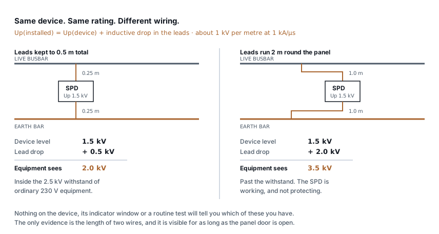 Panels, protection & earthing
SPD installation: the two wires that decide
An SPD with 2 m of lead passes more than twice the voltage it should. Lead length, Uc and type selection, and how to check a panel you did not build.
7 min read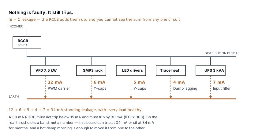 Panels, protection & earthing
RCCB keeps tripping: how to find the leakage
Healthy loads leak. Six of them on one board can trip a 30 mA RCCB with nothing faulty anywhere. How to measure the standing leakage and what to change.
8 min read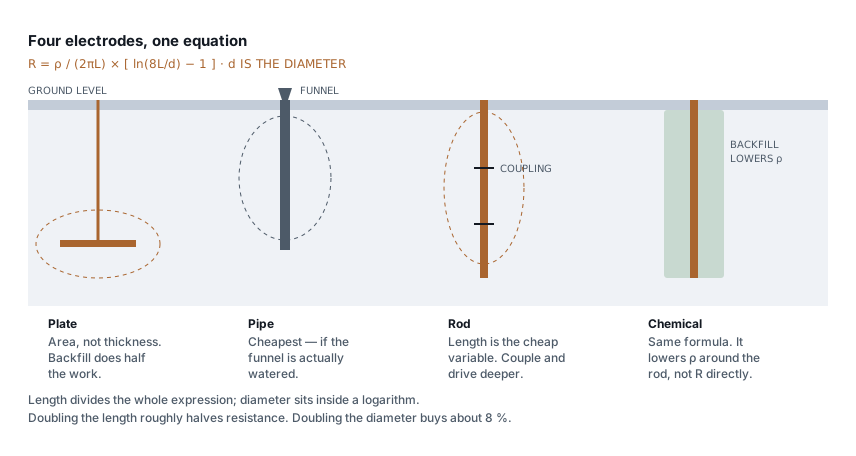 Panels, protection & earthing
Types of earthing: plate, pipe, rod and chemical compared
Plate, pipe, rod and chemical earthing all obey one formula. What separates them is soil resistivity, depth and who maintains them — not the electrode material.
7 min read
Comments
Loading…