
Types of earthing: plate, pipe, rod and chemical compared
Plate, pipe, rod and chemical earthing all obey one formula. What separates them is soil resistivity, depth and who maintains them — not the electrode material.
Every comparison of earthing electrodes lists four types, gives each a formula and a photograph, and stops. After twenty years of digging pits you learn that the choice is almost never about the electrode. It is about the soil you are putting it into and whether anyone will ever come back to maintain it.
Here is what actually separates them.
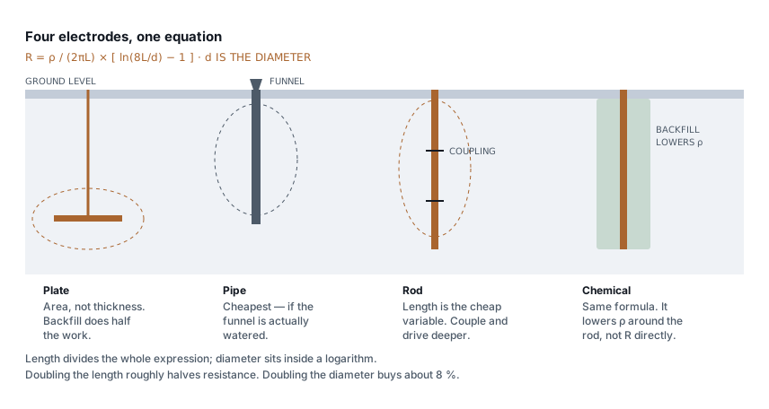
They share one equation
Pipe, rod and chemical electrodes are all vertical conductors in soil, and they all obey the same relationship — Dwight's equation:
R = ρ / (2πL) × [ ln(8L/d) − 1 ]

ρ = soil resistivity, Ω·m
L = length in contact with soil, m
d = electrode diameter, m
Watch the form of that logarithm. You will see it written two ways:
ln(8L/d) when d is the diameter, and ln(4L/a) when a is the
radius. They are the same equation. Mix them — write 4L/d with a diameter
— and you get an answer about 13 % low. For a 3 m rod, 40 mm across, in 100 Ω·m
soil, the difference is 24.9 Ω against the correct 28.6 Ω.
Under-reading earth resistance is the wrong direction to be wrong in, and I have seen that mistake pass a design review because the formula looked right.
What the equation tells you, if you read it
Three things fall straight out of it, and they are worth more than the four type descriptions put together.
Length beats diameter, heavily. L divides the whole expression. d sits
inside a logarithm. Double the length and resistance roughly halves. Double the
diameter and it falls by about 8 %. This is why a 3 m rod outperforms a fat
short one, and why "we used a bigger pipe" is almost never the answer to a
failed reading.
Soil resistivity is a straight multiplier. Halve ρ and you halve R. No
electrode geometry competes with that, which is the entire reason chemical
earthing works.
Depth is free performance. Deep soil holds moisture when the surface dries. An electrode that reads 5 Ω in February and 25 Ω in May was never a 5 Ω electrode — it was a shallow one measured at the right time of year.
Plate earthing
A copper or GI plate, buried flat, usually 600 × 600 mm.
The formula for a plate is not the rod equation, and it is governed by the plate's area, not its thickness. If you see a plate formula with thickness in the denominator, it is mislabelled — that would mean a 3 mm plate has twice the resistance of a 6 mm one, which is not what a plate does. Thickness buys corrosion life, not conductance.
Use it when you have soft soil you can excavate to depth, and the pit will be built properly with alternating layers of charcoal and salt.
The catch nobody mentions: a plate needs a large excavation, and the backfill around it is doing half the work. Dig a 3 m pit, drop in a plate, backfill with the spoil you took out, and you have an expensive rod. Most under-performing plate earths I have measured were backfill failures, not plate failures.
Pipe earthing
A GI pipe, typically 40 mm, driven or set in a pit, with the classic funnel and watering arrangement at the top.
Use it when cost matters and somebody will actually pour water down the funnel.
That last clause is the whole point. Pipe earthing is designed around maintenance. The funnel is not decoration; it exists because the design assumes the soil around the electrode gets wetted periodically. On a site with a maintenance team it is the most economical thing you can install. On an unmanned site it degrades quietly and the funnel fills with rubbish.
GI also corrodes. In aggressive soil — high salinity, low pH, near-coastal — a GI pipe can lose its zinc in a few years and then its section. That is not a reason to avoid it; it is a reason to know your soil before specifying it.
Rod earthing
Solid copper or, far more commonly, copper-bonded steel, driven directly into the ground. Sections couple together so you can keep going.
Use it when the ground is hard, when you have no room to excavate, or when you need depth. This is the one that wins on the equation, because driving is the cheapest way to buy length.
Copper-bonded steel is the sensible default: the steel core takes the driving force, the copper gives the corrosion resistance. Check the copper thickness — 250 microns is the usual specification, and thin plating is the standard economy that turns a thirty-year electrode into a five-year one. You cannot see the difference on delivery.
Rods also let you fix a bad reading without redesigning. Add another section, drive deeper, measure again.
Chemical earthing
A rod inside a pipe filled with a hygroscopic compound, surrounded by a backfill of bentonite or a proprietary mix.
Here is the part the marketing never explains. The formula does not change. A chemical electrode is a rod, and it obeys Dwight's equation exactly like any other rod. What changes is the inputs:
- The backfill lowers
ρin the volume immediately around the electrode — and as the first post in this series notes, most of an electrode's resistance lives in the first metre of soil around it. - The backfill column increases the effective diameter from the rod's 40 mm to the 150–200 mm of the bore.
That second effect is inside a logarithm, so it is modest. The first is the real mechanism, and it is a straight multiplier. Anyone selling you chemical earthing on the strength of the electrode itself is selling you the wrong feature.
Use it when soil resistivity is genuinely high and you cannot solve it with depth — rocky terrain, sandy soil, or a site where you need a low reading for sensitive equipment and conventional electrodes will not get there.
Be honest about the lifetime. The compound is consumed. Manufacturers quote decades; the real figure depends on rainfall and drainage, and a chemical electrode with an exhausted backfill is a plain rod in bad soil. If nobody is going to test it, you have bought a lower reading on the commissioning certificate and not much else.
How to actually choose
Measure the soil first. Everything above is guesswork without a resistivity figure, and a Wenner four-probe survey costs a fraction of the electrodes you are about to specify. It also tells you how resistivity changes with depth, which is what decides whether driving deeper will help.
Then:
| Situation | What to install |
|---|---|
| Soft soil, depth available, maintenance team on site | Plate or pipe |
| Hard or rocky ground, no excavation possible | Driven rod, coupled sections |
| High resistivity that depth will not fix | Chemical, with a testing plan |
| Unmanned site, no maintenance expected | Rod — the least dependent on upkeep |
| Aggressive soil, coastal or low pH | Copper or copper-bonded, not bare GI |
And whatever you install, more electrodes beats a better electrode — up to a point. Rods in parallel do not divide resistance cleanly because each one sits partly inside its neighbour's zone of influence. Space them at least twice their driven length apart or you are paying for copper that competes with itself.
The three things that actually go wrong
Not electrode selection. In order of how often I have found them:
- The connection, not the electrode. A corroded or loose clamp between the conductor and the electrode puts an unknown resistance in series with a carefully calculated one. Exothermic welding removes the joint from the problem entirely.
- No test point. An earth pit with no inspection chamber and no disconnecting link cannot be tested without digging. So it never gets tested.
- Measuring at the wrong time of year. Commission in the monsoon and the reading flatters you. The figure that matters is the one at the end of the dry season, and if you have not measured then, you do not know your earth resistance — you know its best case.
The full design method, soil resistivity ranges and pit construction are covered in earthing design under IS 3043.
Standards referenced
- IS 3043 — Code of Practice for Earthing. Bureau of Indian Standards
Titles are given as commonly published. Check the current edition with the publisher before relying on a clause in professional work.
Related articles
More on panels, protection & earthing.
 Panels, protection & earthing
Earth resistance testing: the 62 % rule, and when the clamp-on lies
Fall-of-potential done properly, the three-position check that proves it, IS 3043 limits by application, and when a clamp-on tester measures nothing.
8 min read Panels, protection & earthing
SPD installation: the two wires that decide
An SPD with 2 m of lead passes more than twice the voltage it should. Lead length, Uc and type selection, and how to check a panel you did not build.
7 min read Panels, protection & earthing
RCCB keeps tripping: how to find the leakage
Healthy loads leak. Six of them on one board can trip a 30 mA RCCB with nothing faulty anywhere. How to measure the standing leakage and what to change.
8 min read Panels, protection & earthing
IP ratings for panels: what IP54, IP65 and IP66 survive
What each digit is tested against, why a higher rating derates your busbars, and the condensation problem that ruins sealed outdoor enclosures.
8 min read
Comments
Loading…