
Busbar sizing: current rating, heat and short-circuit forces
Why amps per mm² is not a constant, what paralleling really buys, and the mechanical force a fault puts on the supports — with the arithmetic worked.
A busbar has to do two unrelated things. It has to carry the continuous current without getting too hot, and it has to survive a fault without being torn off its supports. The first is a thermal problem, the second is mechanical, and they are sized by completely different arithmetic.
Panels usually get the first roughly right using a rule of thumb, and never check the second at all.
Amps per mm² is not a constant
Ask around a panel shop and you will be told copper carries 1.6 A/mm². Apply that to a 12 × 3 bar and you get 58 A, when the real figure is nearer 110. Apply it to a 120 × 10 and you get 1,920 A, which is optimistic by a wide margin.
The rule is only true near the size the person quoting it usually works with.
The physics is straightforward. A bar generates heat throughout its cross-section and sheds it from its surface. Double the area and the surface does not double, so the current each square millimetre can sustain has to fall.
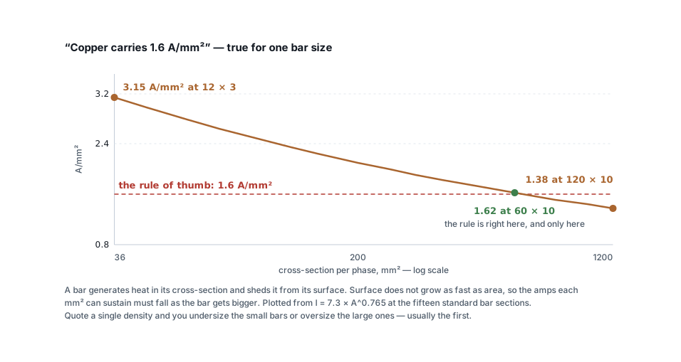
Fitting a power law to published manufacturer tables gives a usable model:
I ≈ C × A^0.765        A in mm²
C = 7.3 copper, 4.6 aluminium
(bare bar, still air, 30 K rise over 40 °C ambient)
That tracks real tables within a few per cent from 12 × 3 up to 120 × 10, which is close enough to choose a bar and quote it. The busbar sizing calculator uses it directly.
It is not a substitute for a type test. An assembly to IS/IEC 61439 is rated by measured temperature rise on the actual panel, and the enclosure, the joint quality and the cable entries all change the answer. Calculate to choose the bar; test to declare a rating.
Paralleling has diminishing returns
Bars in parallel do not add up:
| Bars per phase | Capacity vs one bar |
|---|---|
| 2 | 1.8× |
| 3 | 2.5× |
| 4 | 3.1× |
Two effects work against you. The inner faces of bars sitting 5–10 mm apart radiate into each other rather than into the air, and at 50 Hz the proximity effect pushes current towards the outer faces so the metal in the middle carries less.
By the fourth bar you are paying for copper that does very little. Past three or four bars per phase, a sandwich arrangement or a type-tested busbar trunking system is the better buy.
This is also why bar shape matters more than bar area at large sizes. Skin effect confines current towards the surface at 50 Hz, so a tall thin section outperforms a square one of the same area — the tall bar has more surface for the same metal, both for carrying current and for shedding heat. It is the reason busbars are flat strips rather than square rods, and the reason very large systems move to tubular or channel sections rather than simply stacking more flat bars.
Derate for the panel, not the room
The ambient that matters is the air inside the enclosure, and on a loaded panel in an Indian plant room that runs 10–15 °C above the room temperature.
| Condition | Factor |
|---|---|
| 40 °C internal ambient | 1.00 |
| 45 °C | 0.95 |
| 50 °C | 0.90 |
| 55 °C | 0.84 |
| Ventilated enclosure | 0.90 |
| Sealed IP54+ enclosure | 0.80 |
A 50 °C internal ambient in a sealed enclosure is 0.90 × 0.80 = 0.72. Nearly a third of the bar rating gone, and none of it visible on a drawing that just says "1600 A busbar".
Now the mechanical half
Two parallel conductors carrying current in opposite directions push each other apart. The force goes with the square of the current:
F = 2 × 10⁻⁷ × I²peak / d newtons per metre
Use the peak asymmetrical current, roughly 2.5 times the symmetrical rms value for LV systems. Worked through for a 25 kA board with bars 75 mm apart:
Peak = 25,000 × 2.5 = 62,500 A
F    = 2 × 10⁻⁷ × 62,500² / 0.075
     = 10,417 N/m
Over a tonne per metre, for a few milliseconds, trying to tear the bars off their insulators. That is what busbar supports are for, and it is why their spacing tightens as fault level rises.
Two relationships worth carrying in your head:
- Halve the phase spacing and you double the force.
- Double the fault current and you quadruple it.
Which means a panel that was fine on a 10 kA supply is not automatically fine after the transformer is uprated. Fault level scales with transformer kVA — check it with the transformer sizing calculator — and the bracing has to be rechecked along with the breaking capacity.
Two ratings, two failure modes
It is worth being precise about the two short-circuit numbers, because they get conflated:
| Rating | Symbol | What it means |
|---|---|---|
| Short-time withstand | Icw | The rms current the assembly carries for 1 s (or 3 s) without damage — a thermal limit |
| Peak withstand | Ipk | The instantaneous peak it survives without mechanical failure — a mechanical limit |
A busbar can have plenty of one and not enough of the other. Icw is about the copper getting too hot; Ipk is about the supports letting go. Both must exceed what your system can deliver.
Joints are what actually fail
In service, panels rarely fail because the bar was a size small. They fail at the joints, and the failure mode is always the same: a joint with poor contact heats, which oxidises the surface, which worsens the contact, which makes it hotter.
- Overlap by at least the bar width, with a minimum of two bolts.
- Torque to specification with a torque wrench. Under-tightened joints run hot; over-tightened ones creep and relax.
- Belleville washers on aluminium, always. Aluminium creeps under sustained load and a flat-washer joint loses its clamping force within a year.
- Clean and compound aluminium faces immediately before bolting. Aluminium oxide forms within minutes and it is an insulator.
- Bimetallic connectors where aluminium meets copper. Direct contact in a damp panel is a galvanic cell.
- Thermal-image the panel at full load after commissioning, and again annually. Every joint should be within a few degrees of its bar. The one that is not is the one that will fail.
Clearances are part of the busbar design
The bars themselves are only half the geometry. Air is the insulation between them, and how much you need depends on the voltage and on how dirty the air is going to get.
For a 415 V system, common working minimums inside an assembly are 20 mm phase-to-phase and 20 mm phase-to-earth in clean conditions, opening up as the pollution degree rises. IS/IEC 61439 sets them properly against pollution degree and impulse withstand, and a type-tested assembly has them verified rather than assumed.
Two practical points that catch people:
- Creepage is not clearance. Clearance is the shortest path through air; creepage is the path across an insulating surface. Dust and condensation track across surfaces, so creepage distances are longer, and a support insulator with a ribbed profile is buying creepage rather than looking decorative.
- Sleeving the bars does not license shorter spacing unless the assembly was tested that way. Heat-shrink sleeving is a barrier against accidental contact and a phase-identification aid; treating it as insulation that permits closer bars is a common and untested assumption.
Remember also that reducing phase spacing to fit a narrower chamber doubles the short-circuit force for every halving of the gap. The clearance decision and the bracing decision are the same decision.
Sizing the neutral and earth bars
The phase bars get the attention and the other two get a rule of thumb, which is usually fine and occasionally badly wrong.
The neutral is traditionally half the phase cross-section on a balanced three-phase board, and that holds where the load really is balanced and linear. It stops holding where triplen harmonics are present — third-harmonic currents from single-phase electronics and LED drivers are in phase across all three lines and add in the neutral instead of cancelling. On an office or retail board, a full-size neutral is the safer specification, and where third harmonic exceeds about a third of the line current the neutral is the conductor that sizes the chamber.
The earth bar is sized on fault energy, not on load: S ≥ √(I²t) / k, the
same adiabatic relationship that sizes a protective conductor. It carries
nothing at all until something fails, and then it carries everything for as
long as the breaker takes to clear — which is why a slower upstream device
means a larger earth bar, not just a larger cable.
Specifying a busbar chamber
- Continuous current — usually the incomer rating, not the connected load.
- Bar material and arrangement, derated for the internal ambient and the enclosure.
- Icw and Ipk at or above the system fault level, from the transformer impedance.
- Support spacing checked against the calculated force.
- Phase spacing and clearances stated on the drawing, because they change the force.
- Joint torque specified, and re-torque scheduled at first maintenance.
Run the numbers with the busbar sizing calculator — it selects a standard bar section for your current and conditions, and reports the force per metre and an indicative support spacing from your fault level.
Standards referenced
- IEC 61439 — Low-voltage switchgear and controlgear assemblies. International Electrotechnical Commission
Titles are given as commonly published. Check the current edition with the publisher before relying on a clause in professional work.
Related articles
More on panels, protection & earthing.
 Panels, protection & earthing
Earth resistance testing: the 62 % rule, and when the clamp-on lies
Fall-of-potential done properly, the three-position check that proves it, IS 3043 limits by application, and when a clamp-on tester measures nothing.
8 min read Panels, protection & earthing
SPD installation: the two wires that decide
An SPD with 2 m of lead passes more than twice the voltage it should. Lead length, Uc and type selection, and how to check a panel you did not build.
7 min read Panels, protection & earthing
RCCB keeps tripping: how to find the leakage
Healthy loads leak. Six of them on one board can trip a 30 mA RCCB with nothing faulty anywhere. How to measure the standing leakage and what to change.
8 min read Panels, protection & earthing
Types of earthing: plate, pipe, rod and chemical compared
Plate, pipe, rod and chemical earthing all obey one formula. What separates them is soil resistivity, depth and who maintains them — not the electrode material.
7 min read
Comments
Loading…