
Motor full load current at 415 V: the chart, and the caveats
Full load current for standard three-phase motors from 0.75 to 160 kW, with contactor, relay and cable figures — and why the nameplate rarely matches the table.
Everyone who quotes panels keeps a motor full load current chart somewhere — taped inside a cupboard door, in a spreadsheet, or in their head for the sizes they meet most often. It answers the question that starts every motor circuit: how many amps, so what contactor, what relay, what cable.
Here is the chart for 415 V three-phase motors, followed by the part that matters more — why the number on the nameplate in front of you is usually several per cent higher than the number in any chart, and which one to design to.
The chart
Calculated from I = kW × 1000 / (√3 × 415 × pf × η) with efficiency and power
factor typical of IE3 motors at each rating. Protection figures follow the usual
rules: overload relay set at full load current, cable rated at 1.25 times it.
| kW | HP | Full load current | Contactor (AC-3) | MPCB / MCCB | Cable must carry |
|---|---|---|---|---|---|
| 0.75 | 1 | 1.7 A | 9 A | 2.5 A | 2.1 A |
| 1.5 | 2 | 3.1 A | 9 A | 4 A | 3.9 A |
| 2.2 | 3 | 4.4 A | 9 A | 6.3 A | 5.5 A |
| 3.7 | 5 | 7.1 A | 9 A | 10 A | 8.9 A |
| 5.5 | 7.5 | 10.3 A | 12 A | 16 A | 12.9 A |
| 7.5 | 10 | 13.7 A | 18 A | 16 A | 17.1 A |
| 11 | 15 | 19.6 A | 25 A | 20 A | 24.5 A |
| 15 | 20 | 26.6 A | 32 A | 32 A | 33.3 A |
| 18.5 | 25 | 32.3 A | 38 A | 40 A | 40.4 A |
| 22 | 30 | 38.2 A | 40 A | 40 A | 47.8 A |
| 30 | 40 | 51.7 A | 65 A | 63 A | 64.6 A |
| 37 | 50 | 63.5 A | 65 A | 80 A | 79.4 A |
| 45 | 60 | 76.9 A | 80 A | 80 A | 96.1 A |
| 55 | 75 | 93.6 A | 95 A | 100 A | 117.0 A |
| 75 | 100 | 125.3 A | 150 A | 160 A | 156.6 A |
| 90 | 125 | 149.8 A | 150 A | 160 A | 187.3 A |
| 110 | 150 | 182.3 A | 185 A | 200 A | 227.9 A |
| 132 | 180 | 218.3 A | 225 A | 250 A | 272.9 A |
| 160 | 215 | 264.0 A | 265 A | 320 A | 330.0 A |
For a star–delta starter, the main and delta contactors each carry the winding current — full load current divided by √3, or 0.58 times the figure above — and the star contactor about a third. A 30 kW star–delta needs three contactors around 32 A and 18 A rather than one 65 A.
The motor starter calculator works all of this for any rating, voltage, power factor and starting method, including the star–delta split.
Why the nameplate says something different
Take any motor from the chart and compare it with the plate on the machine. The plate will usually read 5–10 % higher. Neither is wrong.
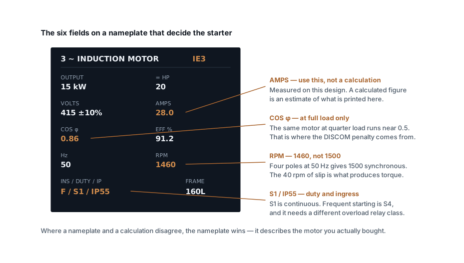
A chart has to assume a power factor and an efficiency, because it is generated from a formula. A nameplate reports what that specific design actually drew on test. The differences come from real things:
- Smaller motors are worse on both counts. A 0.75 kW motor might run at 0.75 power factor and 82 % efficiency; a 160 kW at 0.88 and 96 %. The gap between chart and plate is widest at the bottom of the range.
- Efficiency class. An IE2 motor draws more current than an IE3 of the same output. Charts written before IE3 became mandatory read high; charts written for IE4 read low.
- Pole count. A 6-pole or 8-pole motor of the same kW has a poorer power factor than a 4-pole, and draws more current. Most charts, including this one, assume 4-pole.
- Design voltage. A motor wound for 400 V and run on 415 V draws slightly less current than the chart suggests, and vice versa.
Where they disagree, use the nameplate. It describes the motor you bought. Use the chart for quotations, for sizing before the motor is selected, and as a sanity check when a nameplate looks wrong — a plate reading 20 % away from the chart usually means a different pole count, a different voltage, or a plate from a different machine.
Full load current is not the only current
Three currents matter on a motor circuit and they are far apart:
| Current | Roughly | Sets |
|---|---|---|
| Full load | 1× | Overload relay, cable size, contactor |
| Starting (DOL) | 6–7× | Volt drop during start, generator sizing, magnetic trip setting |
| Locked rotor | 6–8× sustained | What the relay must trip on before the winding cooks |
A 15 kW motor at 26.6 A draws around 175 A on a direct-on-line start. That current is why the breaker on a motor circuit must have a C or D curve — a B-curve device trips magnetically at three to five times rating and will never let the motor start — and why the cable to a motor at the end of a long run should be checked for volt drop at starting current, not only at running current.
Reading the rest of the plate
The current is what you came for, but four other fields change the design:
Duty (S1 to S9). S1 is continuous, and everything in the chart above assumes it. A motor that starts twenty times an hour is S4 or S5 duty and needs a class 20 or class 30 overload relay — a standard class 10 relay will trip on accumulated starting current even though nothing is wrong.
Service factor. If the plate carries one — 1.15 is common on motors built to NEMA practice — the relay may be set up to 1.15 times full load current. If there is no service factor marked, set it at 1.0.
Insulation class. Class F insulation with a class B temperature rise is the common specification, and the margin between them is what lets the motor tolerate a hot day. A motor run at class F rise has no margin left.
IP rating. IP55 is standard for industrial duty. Outdoor or washdown locations need IP65 or IP66, and it applies to the terminal box as much as the frame — which is where water usually gets in.
Voltages other than 415 V
The chart assumes 415 V. Current scales inversely with voltage for the same power, so you can move between the common LT voltages without recalculating from scratch:
I(new) = I(415) × 415 / V(new)
| Supply | Multiply the chart by |
|---|---|
| 380 V | 1.09 |
| 400 V | 1.04 |
| 415 V | 1.00 |
| 440 V | 0.94 |
| 690 V | 0.60 |
That last row is the reason large motors move to 690 V where the supply allows it. A 160 kW motor drops from 264 A to about 159 A, and the cable, the contactor and the busbar all come down with it.
The scaling holds for the current. It does not hold for the motor: a machine wound for 400 V and run at 415 V draws slightly less current than the arithmetic suggests, because it is being run marginally above its design voltage. Use it to move between chart rows, not to justify running a motor on a supply it was not wound for.
A rewound motor is not the motor on the chart
Rewinding is normal practice and often the right economic call, but it changes the numbers this chart is built on. A competent rewind typically costs 0.5–1 % of efficiency; a poor one — wrong wire gauge, overheated core steel during stripping, changed slot fill — can cost 2–4 %.
Efficiency sits in the denominator of the full load current calculation, so every point lost raises the current the motor draws for the same shaft output. A motor rewound twice can be drawing meaningfully more than its plate says while delivering exactly what it always did.
Two practical consequences. The overload relay setting should be checked against a measured current after a rewind, not left where it was. And on a motor that has been rewound more than once, the economics of replacement with an IE3 machine are usually better than they look, because you are comparing against a degraded baseline rather than the nameplate.
Two mistakes this chart will not save you from
Sizing the cable to the contactor. The contactor is chosen from a standard range and is often well above the motor's actual current — a 22 kW motor at 38.2 A gets a 40 A contactor. The cable is sized from 1.25 times the motor current, 47.8 A, not from the contactor rating. Then it is derated for ambient, grouping and installation method, which on a hot cable tray can push it up two sizes. Work it through with the cable sizing calculator.
Adding nameplate currents to size the incomer. Motors rarely all run at once and almost never all at full load. Sizing a board on the sum of every nameplate gives an incomer and a transformer far larger than the plant will ever draw — apply a demand factor, or better, measure. The three-phase current calculator converts a measured or estimated demand into current for the supply side.
One caution on the chart itself: the efficiency and power factor behind each row are typical, not guaranteed. For a design being issued for construction, use the motor manufacturer's data sheet. For a quotation, this is close enough that the switchgear you price will be the switchgear you fit.
Related articles
More on motors & starting.
 Motors & starting
Choosing a VFD: what actually decides the size
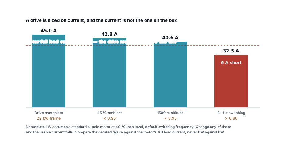
Drives are sized on current, not kW — and the current on the box is before derating. Overload class, control mode, cable length and harmonics.
7 min read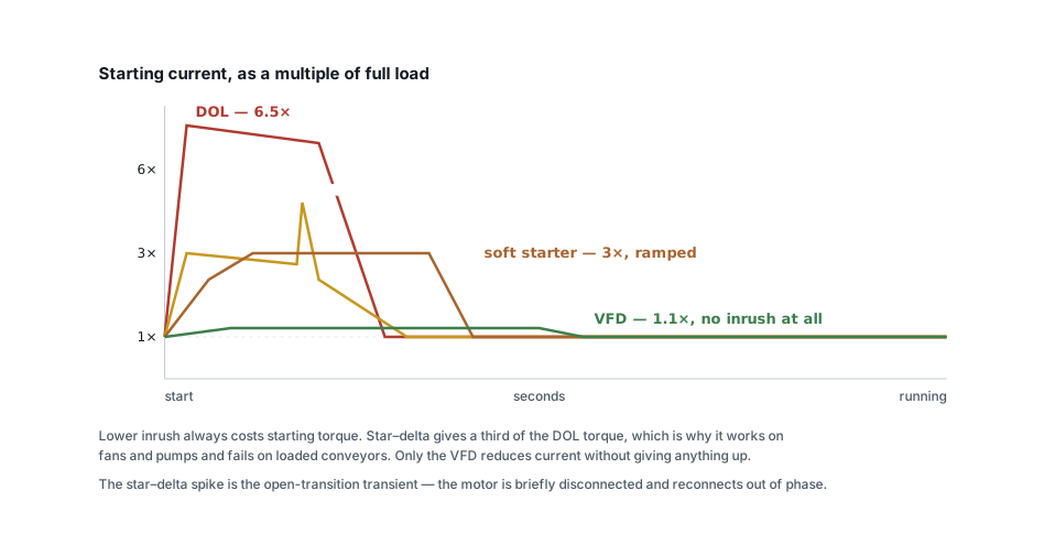 Motors & starting
DOL, star–delta, soft starter or VFD: how to choose
Inrush is only half the decision. What each starter does to torque, which loads each suits, and the four failure modes that follow the wrong choice.
6 min read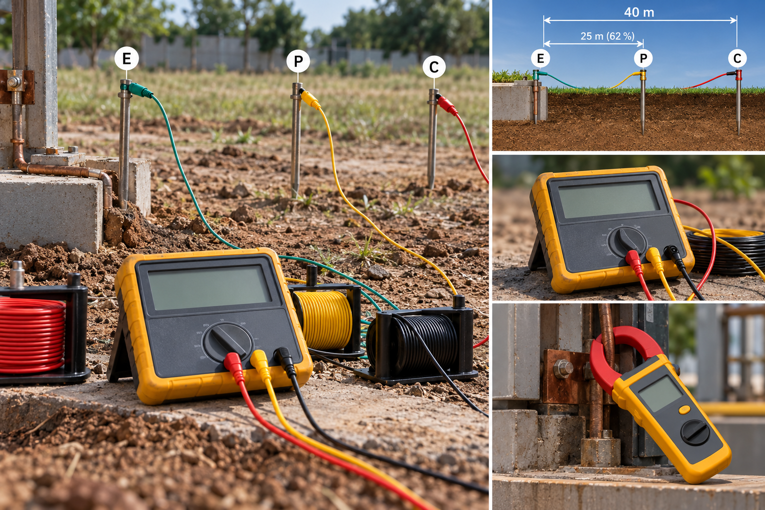 Panels, protection & earthing
Earth resistance testing: the 62 % rule, and when the clamp-on lies
Fall-of-potential done properly, the three-position check that proves it, IS 3043 limits by application, and when a clamp-on tester measures nothing.
8 min read Cable sizing
Cable size for large loads: when to run cables in parallel
Above 300 mm², a bigger cable size stops paying. When to run cables in parallel, the six rules for equal sharing, and the overload no breaker can see.
10 min read
Comments
Loading…