
Choosing a VFD: what actually decides the size
Drives are sized on current, not kW — and the current on the box is before derating. Overload class, control mode, cable length and harmonics.
A variable frequency drive is usually specified by matching kilowatts: 22 kW motor, 22 kW drive, done. That works often enough to be a habit and fails in a way that is expensive to discover, because the drive runs fine on the bench and trips on overload in August.
Drives are rated in current. The kilowatt figure on the box is a convenience label that assumes a standard four-pole motor at 400 V, 40 °C, sea level and the factory switching frequency. Change any of those and the usable current falls.
Size on current, then derate
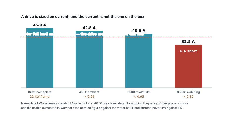
Start with the motor's full load current from its nameplate — not from a chart, and not from its kW rating. Then apply what your installation does to the drive:
| Condition | Typical factor |
|---|---|
| Ambient above 40 °C | −2 % per °C, to about 50 °C |
| Altitude above 1000 m | −1 % per 100 m |
| Switching frequency raised from 4 to 8 kHz | −15 to −25 % |
| Switching frequency raised to 12 kHz | −30 to −40 % |
The switching frequency one surprises people. Raising it makes the motor quieter and the current waveform smoother, and it is often turned up during commissioning by somebody solving an audible-noise complaint. It also increases switching losses in the IGBTs, which is paid for in continuous current. A drive set to 8 kHz can be a fifth smaller than the one you ordered.
Work the motor current out with the three-phase current calculator if you have kW but no nameplate — and remember the nameplate wins whenever the two disagree.
Overload class is not a detail
Every drive has two ratings, and the catalogue leads with the flattering one.
| Rating | Overload | For |
|---|---|---|
| Normal duty / variable torque | 110 % for 60 s | Centrifugal fans and pumps |
| Heavy duty / constant torque | 150 % for 60 s | Conveyors, mixers, compressors, crushers |
The same physical drive is often sold as, say, 22 kW normal duty and 18.5 kW heavy duty. Specify from the catalogue's headline number for a conveyor and you have bought a drive one frame too small.
The load's torque curve decides which column you are in:
- Torque rising with speed² — centrifugal fans and pumps. Almost no torque at standstill, so normal duty is genuinely enough.
- Constant torque — conveyors, positive displacement pumps, extruders. Full torque from zero. Heavy duty.
- High breakaway — crushers, mixers starting loaded, anything that may start against a jam. Heavy duty, and consider a frame above it.
Control mode
Three levels, and paying for the top one when you need the bottom one is wasteful; the reverse does not work at all.
V/f (scalar) holds a fixed volts-per-hertz ratio. Simple, robust, and the only mode that will drive several motors from one drive. Torque falls away below about 10 Hz, so it suits fans and pumps and little else.
Sensorless vector estimates rotor position from the current waveform and gives close to full torque down to 1–2 Hz. This is what a conveyor that must start loaded needs, and it is the sensible default for anything that is not a fan. One drive, one motor.
Closed-loop vector adds an encoder for full torque at zero speed and precise speed holding. Hoists, positioning, winders. It brings an encoder, its cable and its failure modes with it — do not specify it unless the application genuinely needs standstill torque.
Four things that damage motors, not drives
A drive's output is a train of steep-edged pulses, not a sine wave, and that has consequences the datasheet does not lead with.
Reflected wave on long cables. Voltage doubling at the motor terminals gets worse with cable length and faster IGBT edges. Beyond roughly 50 m, fit an output reactor or a dV/dt filter; beyond 100 m, a sine filter is often the honest answer. Ignoring it punctures winding insulation over months.
Bearing currents. Common-mode voltage discharges through the bearing races and pits them. Above about 100 kW — sooner on 690 V systems — specify an insulated non-drive-end bearing or a shaft grounding ring.
Cooling at low speed. A standard motor is cooled by a fan on its own shaft. Run it at 20 Hz for hours and it is producing heat with almost no airflow. Constant-torque duty at low speed needs a force-ventilated motor or a derated one.
Insulation class. An inverter-duty motor has reinforced winding insulation for exactly these reasons. Standard motors tolerate drives; inverter-duty motors survive them.
Harmonics, and the reactor you should have specified
A six-pulse drive — which is nearly all of them below a few hundred kW — draws current in pulses, not sinusoidally. Typical current distortion is 35–45 % with nothing fitted.
| Mitigation | Rough current THD |
|---|---|
| Nothing | 35–45 % |
| 3 % line reactor or DC choke | 28–35 % |
| 5 % line reactor | 25–30 % |
| 12-pulse | 10–12 % |
| Active front end | Under 5 % |
A line reactor is cheap, passive and has no failure mode worth worrying about. Specify one on every drive above a few kW unless there is a reason not to — it also protects the drive's input rectifier from supply transients, which is worth the cost on its own.
The reason to care beyond IEEE 519 compliance: harmonic current raises RMS current in every cable and transformer upstream, and it will resonate with any capacitor bank on the same supply. The harmonic loss calculator puts a number on both, and APFC panels covers the detuned reactors that keep a correction bank alive on a drive-heavy site.
Protection, and the two things that are different
A Type B residual current device, not Type AC. A drive's rectifier can produce leakage with a DC component, and DC leakage saturates a Type AC device so it stops detecting the AC leakage it was fitted for — silently. The distinction is set out in MCB, MCCB, ACB and RCCB.
Short-circuit protection is the drive's, not the motor's. The drive protects the motor electronically; the upstream device protects the cable and the drive. Many manufacturers specify semiconductor fuses for the input, and a plain MCCB will not protect the rectifier. Follow the drive manual's table rather than sizing it like a DOL circuit — though the cable itself is still sized the ordinary way with the cable sizing calculator.
What else to settle before ordering
- Panel heat. A drive dissipates roughly 3 % of its rating. Three 22 kW drives put about 2 kW into an enclosure, which is a cooling calculation, not a rounding error — and it derates everything else inside, as in IP ratings for panels.
- EMC filter category. C1 for residential, C2 for most industrial, C3 for restricted-access installations. Built-in filters raise earth leakage, which interacts with your RCD choice.
- Braking. An overhauling load — a hoist, a high-inertia fan coasting down — pushes energy back. That needs a braking resistor sized for the duty cycle, or a regenerative front end.
- A bypass contactor on critical loads, so a failed drive does not stop production while it is replaced.
- Communications. Most drives speak Modbus RTU over RS485 as standard. If they will share a bus with your metering, budget the poll cycle with the RS485 calculator — drives answer slowly.
The order that avoids the expensive mistake
- Motor full load current from the nameplate.
- Load torque curve → normal or heavy duty.
- Apply ambient, altitude and switching frequency derating.
- Confirm the derated continuous current still exceeds the motor's FLC.
- Control mode from the application, not the price list.
- Cable length → output filtering.
- Line reactor, essentially always.
- Type B RCD, and the manufacturer's input protection.
Steps 1 and 3 are the ones people skip, and together they are the reason a drive that matched on kilowatts trips on a hot afternoon in its second summer.
Standards referenced
- IEEE 519 — Recommended Practice and Requirements for Harmonic Control in Electric Power Systems. IEEE
Titles are given as commonly published. Check the current edition with the publisher before relying on a clause in professional work.
Related articles
More on motors & starting.
 Motors & starting
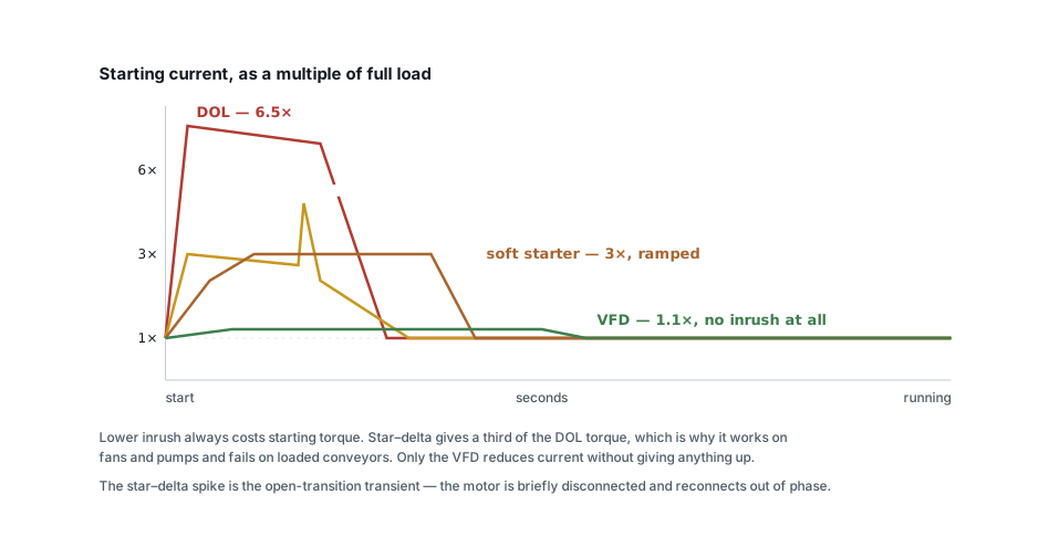
DOL, star–delta, soft starter or VFD: how to choose
Inrush is only half the decision. What each starter does to torque, which loads each suits, and the four failure modes that follow the wrong choice.
6 min read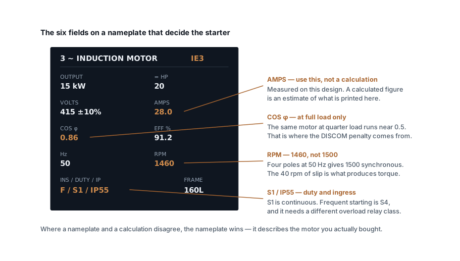 Motors & starting
Motor full load current at 415 V: the chart, and the caveats
Full load current for standard three-phase motors from 0.75 to 160 kW, with contactor, relay and cable figures — and why the nameplate rarely matches the table.
9 min read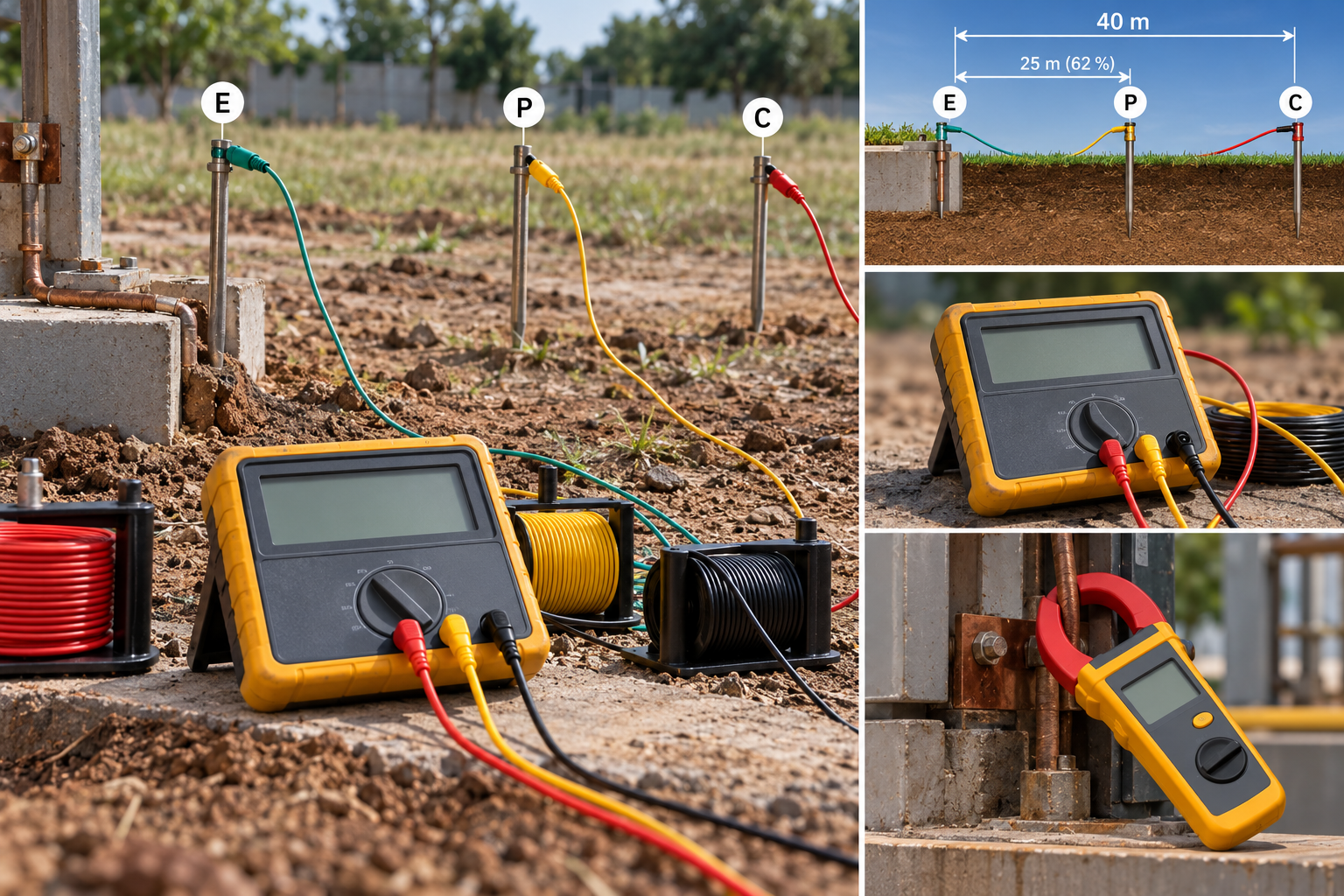 Panels, protection & earthing
Earth resistance testing: the 62 % rule, and when the clamp-on lies
Fall-of-potential done properly, the three-position check that proves it, IS 3043 limits by application, and when a clamp-on tester measures nothing.
8 min read Cable sizing
Cable size for large loads: when to run cables in parallel
Above 300 mm², a bigger cable size stops paying. When to run cables in parallel, the six rules for equal sharing, and the overload no breaker can see.
10 min read
Comments
Loading…