
How to size a cable correctly: the six-step sequence
Design current, derating, tabulated rating, breaker coordination, volt drop and short-circuit withstand — the full sequence, worked through for a 45 kW motor.
Ask ten site engineers how to size a cable and most will describe the same two steps: work out the current, then look up the table. That gets you a cable that is right about half the time. The half that fails does so quietly — the cable does not trip anything, it just runs hot for six years and then the insulation gives up on a Tuesday afternoon.
The full sequence has six steps. Here they are, with a real example.
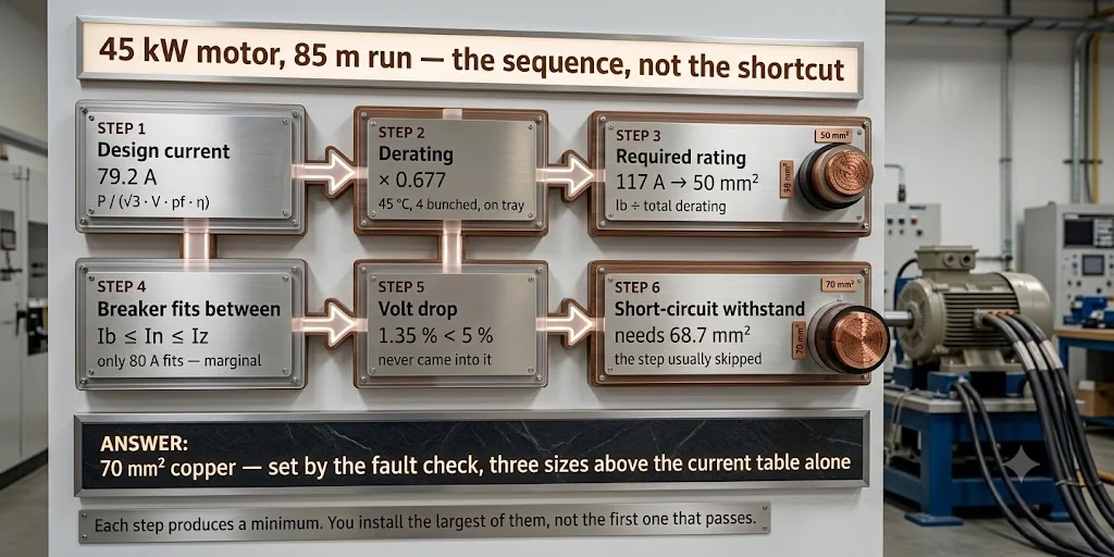
Each step produces a minimum size, and the cable you specify is the largest of them — not the first one that passes. That is the single idea most sizing mistakes come down to: someone finds a size that clears the current table, stops there, and never discovers that volt drop or fault withstand wanted more.
The worked example
A 45 kW induction motor, 415 V three-phase, power factor 0.86, efficiency 0.92. The run is 85 metres from the MCC to the motor, on a perforated tray, bunched with three other cables, in a plant room that reaches 45 °C in May.
Step 1 — Design current
Ib = P / (√3 × V × cos φ × η)

Ib = 45000 / (1.732 × 415 × 0.86 × 0.92)
Ib = 45000 / 568.4
Ib = 79.2 A
Note the efficiency term. A lot of people leave it out, which understates the current by 8–10 % on a typical motor. The motor draws what it draws on the input side, not the shaft side.
The three-phase current calculator does this step on its own if that is all you need, and it shows the apparent and reactive power alongside.
Step 2 — Derating
This is where most designs go wrong. The table value assumes one cable, in free air, at a reference ambient. Your cable is none of those things.
| Condition | This job | Factor |
|---|---|---|
| Ambient 45 °C | plant room in May | 0.95 |
| 4 circuits bunched | on the tray | 0.75 |
| On perforated tray | not free air | 0.95 |
Total derating = 0.95 × 0.75 × 0.95 = 0.677
The cable has lost a third of its capacity before you have chosen it.
Step 3 — Required tabulated rating
Iz ≥ Ib / (Ca × Cg × Ci)

Iz ≥ 79.2 / 0.677
Iz ≥ 117 A
From the copper table, 35 mm² carries 113 A — not enough. 50 mm² at 138 A is the first size that clears it.
If you had skipped derating you would have picked 25 mm² (92 A) and been two sizes light. That cable would run at roughly 127 % of its real capacity.
Step 4 — The breaker has to fit between the two
A cable and its protective device are sized together, and there is a rule that ties them:
Ib ≤ In ≤ Iz
The device rating In must be at least the design current, or it trips on
normal load. It must also not exceed the cable's derated capacity, or the
cable can sit above its rating indefinitely without the breaker ever noticing.
A cable protected by a breaker that is too large is not protected.
Note which Iz this is. Not the table value — the table value after your
derating factors. For the 50 mm² we were about to choose:
Iz(actual) = 138 × 0.677 = 93.4 A
So In has to land between 79.2 A and 93.4 A, and the only standard rating
that fits is 80 A. That is under 1 % above the design current on a motor
circuit, which is uncomfortably tight — you would be relying on the starting
dip never quite reaching it.
Move to 70 mm² and the picture changes:
Iz(actual) = 175 × 0.677 = 118.5 A
79.2 ≤ 100 ≤ 118.5  ✓
A 100 A device fits with room either side. This is a good example of a step that does not strictly fail at 50 mm² but tells you something is wrong — when only one breaker rating fits, and barely, the cable is marginal.
There is a second condition for devices whose tripping characteristic is not
adjustable, I₂ ≤ 1.45 × Iz, where I₂ is the current guaranteeing operation
in the conventional time. Modern MCBs and MCCBs to IS/IEC standards satisfy it
automatically when In ≤ Iz, so in practice it only needs checking with fuses
and older devices.
Motors are the exception worth knowing. Where a starter provides the
overload protection through its own relay, the upstream device is doing
short-circuit protection only and is deliberately sized above Ib — the
In ≤ Iz limit then applies to the overload relay setting, not to the breaker.
Apply the rule to whichever device is actually protecting the cable against
overload.
Step 5 — Volt drop
Now check the run length. For 50 mm² copper, volt drop is 0.83 mV per ampere per metre.
Vd = 0.83 × 79.2 × 85 / 1000 = 5.59 V
Vd% = 5.59 / 415 × 100 = 1.35 %
Comfortably inside the 5 % limit for power circuits. On a longer run — say 250 m — the same cable would give 4.0 %, still passing but close enough that you would go up a size for the motor starting dip.
Volt drop governs more often than people expect. Any run past about 100 m at low voltage, check it before you commit.
The voltage drop calculator will also tell you the longest run a given size can carry within the limit, and the smallest size that clears it — useful when you are deciding between upsizing the cable and moving the board closer.
Step 6 — Short-circuit withstand
The step almost everyone skips. The cable must survive the fault current for as long as the protective device takes to clear it:
S ≥ √(I² t) / k
where k is 115 for PVC-insulated copper and 76 for PVC-insulated aluminium.
If the board fault level is 25 kA and the breaker clears in 0.1 s:
S ≥ √(25000² × 0.1) / 115
S ≥ 7906 / 115
S ≥ 68.7 mm²
Which means 50 mm² fails on short-circuit withstand even though it passed current and volt drop. You need 70 mm².
This is the step that catches good engineers out. A cable sized correctly for load can still be destroyed by a fault it has to hold for a tenth of a second.
There is more to it — the right k for a phase conductor versus a protective
one, what current-limiting devices change, and why the far end of a long cable
needs checking as well as the near end. It has its own post:
short-circuit withstand.
The answer
Laying the six steps out together shows where the decision actually came from:
| Step | Check | Minimum size |
|---|---|---|
| 1 | Design current, 79.2 A | — |
| 2 | Derating, total 0.677 | — |
| 3 | Tabulated rating ≥ 117 A | 50 mm² |
| 4 | Breaker fits between Ib and Iz | 50 mm², marginal |
| 5 | Volt drop 1.35 %, limit 5 % | not governing |
| 6 | Short-circuit withstand ≥ 68.7 mm² | 70 mm² |
70 mm² copper, governed by short-circuit withstand, not by load current.
Read down the last column and the point of the sequence is obvious. Volt drop had plenty of margin on an 85 m run and never came into it, the current table asked for 50 mm², and the fault check — the one most often skipped — is what actually set the answer. Any one step taken alone gives the wrong cable.
If you had used only the current table you would have specified 25 mm² — three sizes light and unsafe under fault.
Try it
The cable sizing calculator runs the current and volt drop steps with the derating factors built in. Short-circuit withstand depends on your board fault level and breaker curve, so check that one against your protection study.
A caution worth repeating
Cable current ratings vary between manufacturers by 5–10 % for the same nominal size and construction. The tables here are representative. Before you issue a design, pull the actual datasheet for the cable you are buying.
Related articles
More on cable sizing.
 Cable sizing
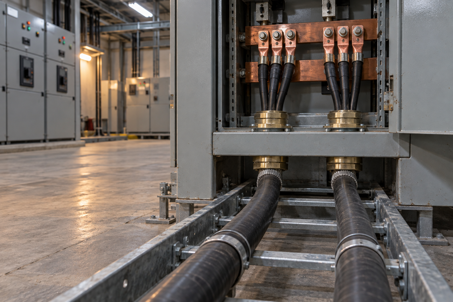
Cable size for large loads: when to run cables in parallel
Above 300 mm², a bigger cable size stops paying. When to run cables in parallel, the six rules for equal sharing, and the overload no breaker can see.
10 min read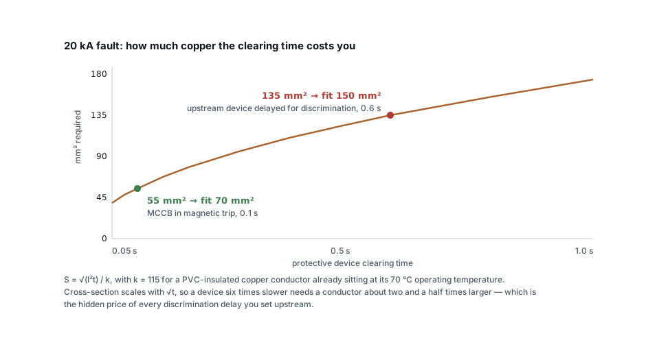 Cable sizing
Short-circuit withstand: the cable check everyone skips
A cable that passes current rating and volt drop can still fail under fault. The adiabatic check, the right k value, and why discrimination delays cost copper.
7 min read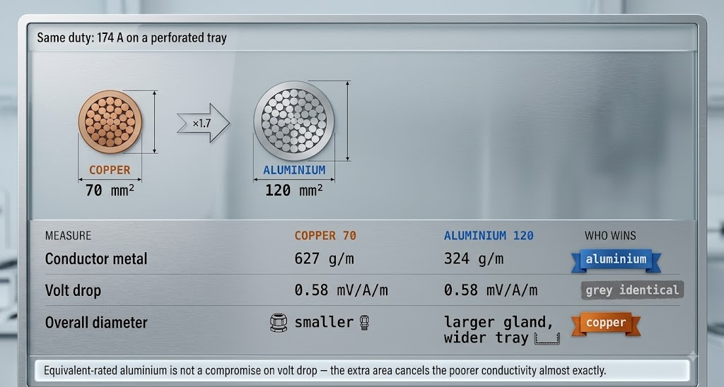 Cable sizing
Copper or aluminium: where aluminium stops being cheaper
Aluminium needs 1.6 times the cross-section for the same current — and still costs less per metre. The crossover, and the four places it goes wrong.
8 min read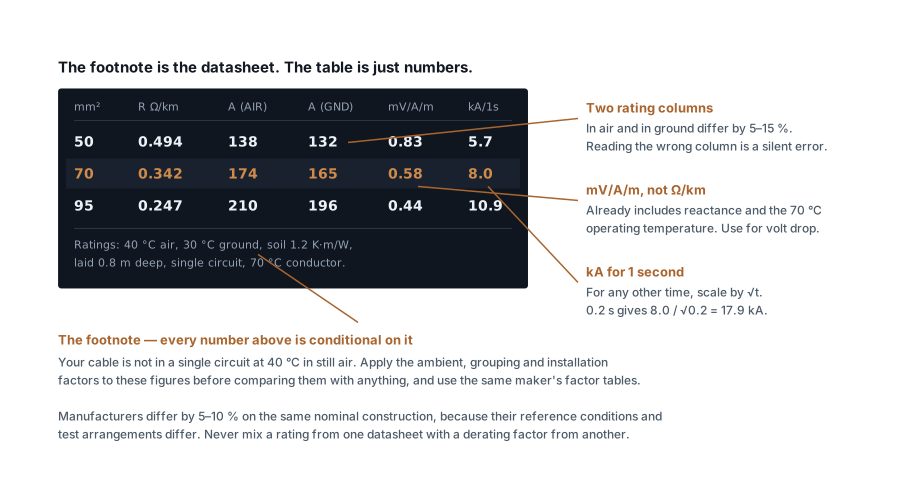 Cable sizing
How to read a cable datasheet without getting caught out
Reference conditions, two rating columns, mV/A/m versus ohms per km, one-second fault ratings and how to decode A2XFY — the fine print that decides the size.
7 min read
Comments
Loading…