
How to read a cable datasheet without getting caught out
Reference conditions, two rating columns, mV/A/m versus ohms per km, one-second fault ratings and how to decode A2XFY — the fine print that decides the size.
A cable datasheet looks like a table of facts. It is really a table of conditional facts, and the condition is in a footnote at the bottom of the page in the smallest type on the sheet. Read the table without the footnote and you will pick cables that are 20 % adrift and never know it.
This is what each column actually means, and the six places a datasheet catches people out.
The footnote is the datasheet
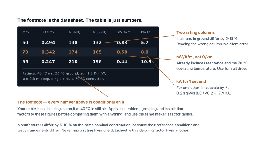
Every current rating on a cable datasheet is published against reference conditions. The Indian convention:
| Condition | Reference |
|---|---|
| Ambient in air | 40 °C |
| Ground temperature | 30 °C |
| Soil thermal resistivity | 1.2 K·m/W |
| Depth of laying | 0.8 m |
| Grouping | One circuit, isolated |
| Conductor temperature | 70 °C PVC, 90 °C XLPE |
Your installation matches none of those. Every departure needs a correction from the derating tables, and the corrections multiply.
The important discipline: use the same manufacturer's rating table and derating factors together. They are derived from the same test arrangement. Mixing a rating from one datasheet with a factor from another produces a number that means nothing, even though both inputs were correct.
Two rating columns, and reading the wrong one
Almost every datasheet publishes at least two current ratings for each size: one for installation in air, one for direct burial in ground. They differ by 5–15 %, and which is higher depends on the size.
Small cables often do better in ground, because 30 °C soil is cooler than 40 °C air. Large cables usually do better in air, because soil conducts heat away slowly and a big cable generates a lot of it.
There is usually a third distinction for single-core cables: trefoil (three cores in a triangle, touching) versus flat spaced. The difference is significant — flat spaced runs cooler and carries more. If the datasheet gives both, the installation drawing has to say which arrangement is intended, or the site will do whatever is easiest and the rating you designed to will not apply.
Resistance is quoted at two temperatures
You will see two resistance figures and they are not interchangeable:
- DC resistance at 20 °C — the manufacturing figure. It is what the cable is tested against on the drum, and it is the one quoted in the conductor standard.
- AC resistance at operating temperature — 70 °C or 90 °C, including skin effect and proximity effect.
For a 70 mm² copper conductor the operating figure is roughly 25 % higher than the 20 °C DC value. Using the 20 °C number for a volt drop calculation understates the drop by about a quarter, which is exactly the sort of error that passes review because the arithmetic is correct.
Skin effect pushes current towards the outside of a conductor at 50 Hz and matters above about 185 mm². Proximity effect does the same when conductors run close together. Both are already inside the AC resistance figure — do not add them again.
Use mV/A/m for volt drop, not ohms per kilometre
The volt drop column is the one to use, and it is not simply resistance converted. It bundles three things: resistance at operating temperature, inductive reactance, and the √3 for a three-phase circuit.
Reactance is why the two are not interchangeable. On small cables resistance dominates and reactance is negligible. Above roughly 95 mm² reactance becomes a real share of the total, and on 300 mm² and larger it can dominate — which is why volt drop stops improving much as you go up in size. Doubling the copper past that point buys very little.
Some datasheets split the column into mVr (resistive) and mVx (reactive)
components, with mVz as the vector sum. Use mVz unless you have a specific
reason to work with the components, and note that the tabulated figure assumes
0.8 power factor unless stated otherwise. At a better power factor the real drop
is slightly lower — a conservative error, but worth knowing when a run is
marginal.
Feed the figure straight into the voltage drop calculator rather than deriving it from resistance.
The short-circuit rating is for one second
The fault column — often kA for 1 s — is the current the conductor can carry
for one second before its insulation reaches the damage temperature. Faults are
almost never one second long.
Scale it with the square root of time:
I(t) = I(1s) / √t
A 70 mm² copper cable rated 8.0 kA for 1 s will take 8.0 / √0.2 = 17.9 kA for 0.2 s. This is the same adiabatic relationship that sizes an earthing conductor, applied to the phase conductor.
Two cautions. The time is the total clearing time of the protective device, including its opening time, not the setting on a relay dial. And a current-limiting device that cuts the fault before the first peak lets through far less energy than the calculation suggests — if you are relying on that, use the device's published let-through energy rather than this column.
Decoding the type designation
Indian cable type codes are systematic once you know the letters. Reading left to right: conductor, insulation, armour, outer sheath.
| Letter | Means |
|---|---|
| A | Aluminium conductor (no A = copper) |
| Y | PVC — as insulation if it appears before the armour, as sheath if after |
| 2X | XLPE insulation |
| W | Round steel wire armour |
| F | Flat steel strip armour |
So:
| Code | Reads as |
|---|---|
| YWY | Copper, PVC insulated, round wire armoured, PVC sheathed |
| A2XFY | Aluminium, XLPE insulated, flat strip armoured, PVC sheathed |
| 2XWY | Copper, XLPE insulated, round wire armoured, PVC sheathed |
| AYY | Aluminium, PVC insulated, unarmoured, PVC sheathed |
Armour choice is not cosmetic. Round wire armour has better tensile strength and suits vertical runs and direct burial where the cable takes pulling load. Flat strip armour is cheaper and adequate for horizontal runs on tray.
Never use steel armour on a single-core AC cable. The alternating field induces eddy currents in the steel, which heats up and derates the cable badly. Single-core cables use aluminium wire armour or none at all — and the same applies to steel gland plates and steel conduit carrying single cores.
What else to check before you order
- Voltage grade. 1.1 kV is standard for LT. Do not accept 650/1100 V marked cable for a 1.1 kV specification without checking which figure is the grade.
- Number of cores. 3.5-core has a reduced neutral — fine for balanced three-phase loads, wrong where the neutral carries harmonic current from VFDs or LED drivers. Then you need a full 4-core.
- Standard. IS 1554 Part 1 for PVC, IS 7098 Part 1 for XLPE. A datasheet that does not cite one is not a datasheet.
- Tolerance. Manufacturers vary 5–10 % on the same nominal construction. Design to the datasheet of the cable you will actually buy; if the procurement team substitutes a brand, the sizing needs rechecking.
- Drum lengths. A 500 m run supplied as two 250 m drums needs a joint, and a joint is a maintenance liability and an extra impedance in the fault loop.
Work the sizing through with the cable sizing calculator using the figures from the actual datasheet, and follow the whole sequence in how to size a cable correctly — the datasheet is the input to that process, not a substitute for it.
Standards referenced
- IS 1554 — PVC Insulated (Heavy Duty) Electric Cables. Bureau of Indian Standards
- IS 7098 — Cross-Linked Polyethylene Insulated Thermoplastic Sheathed Cables. Bureau of Indian Standards
Titles are given as commonly published. Check the current edition with the publisher before relying on a clause in professional work.
Related articles
More on cable sizing.
 Cable sizing
Cable size for large loads: when to run cables in parallel
Above 300 mm², a bigger cable size stops paying. When to run cables in parallel, the six rules for equal sharing, and the overload no breaker can see.
10 min read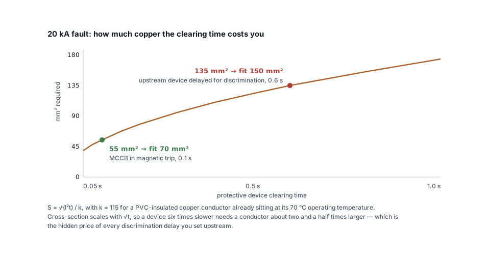 Cable sizing
Short-circuit withstand: the cable check everyone skips
A cable that passes current rating and volt drop can still fail under fault. The adiabatic check, the right k value, and why discrimination delays cost copper.
7 min read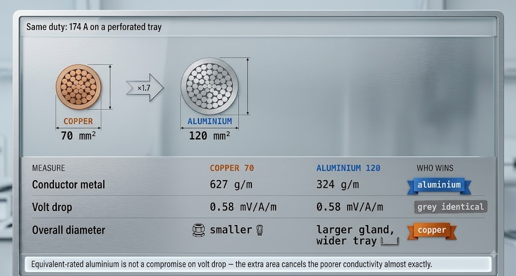 Cable sizing
Copper or aluminium: where aluminium stops being cheaper
Aluminium needs 1.6 times the cross-section for the same current — and still costs less per metre. The crossover, and the four places it goes wrong.
8 min read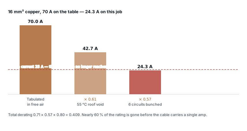 Cable sizing
Cable derating factors: the complete table
Ambient, grouping and installation factors in one place, worked through — plus the four factors that are not in any table but still apply.
11 min read
Comments
Loading…