
Short-circuit withstand: the cable check everyone skips
A cable that passes current rating and volt drop can still fail under fault. The adiabatic check, the right k value, and why discrimination delays cost copper.
Cable sizing usually stops when two conditions are satisfied: the cable carries the load current after derating, and the volt drop is inside the limit. Both are about normal operation. Neither says anything about the two-tenths of a second when a fault is on the system and the cable is carrying twenty thousand amperes.
That is a separate check, it is genuinely capable of picking a larger cable than either of the other two, and it is the one most often left out — including by software that produces a very confident-looking schedule.
What actually happens during a fault
For the fraction of a second before the breaker opens, the fault current flows through the cable. It is far too brief for any of that heat to escape into the surroundings — all of it stays in the conductor and raises its temperature directly.
If the conductor gets hot enough, the insulation is damaged. It may not fail that day. PVC that has been cooked once is brittle, and the circuit that tripped cleanly in March becomes an earth fault in September.
The condition to satisfy:
k² S² ≥ I² t
or, rearranged into the form you actually use:
S ≥ √(I² t) / k
with S the cross-section in mm², I the fault current in amperes, t the total clearing time in seconds, and k a constant for the conductor and insulation.
The k value trips people up
The same conductor has two different k values depending on the job it is doing, and using the wrong one is the commonest mistake in this calculation.
| Conductor | Phase conductor | Protective conductor |
|---|---|---|
| Copper, PVC | 115 | 143 |
| Copper, XLPE | 143 | 176 |
| Aluminium, PVC | 76 | 95 |
| Aluminium, XLPE | 94 | 116 |
Why the difference? A phase conductor is already carrying load current when the fault happens, so it starts at its operating temperature — 70 °C for PVC. A protective conductor normally carries nothing, so it starts at ambient, around 30 °C. The protective conductor has 40 °C more headroom before it reaches the same damage temperature, and that extra margin is what the larger k expresses.
Use the phase-conductor column for the cable you are sizing here. Use the protective-conductor column in the earthing conductor calculator, which is a different calculation with the same equation.
The clearing time is the expensive input
Because cross-section scales with the square root of time, a slow device is punished hard.
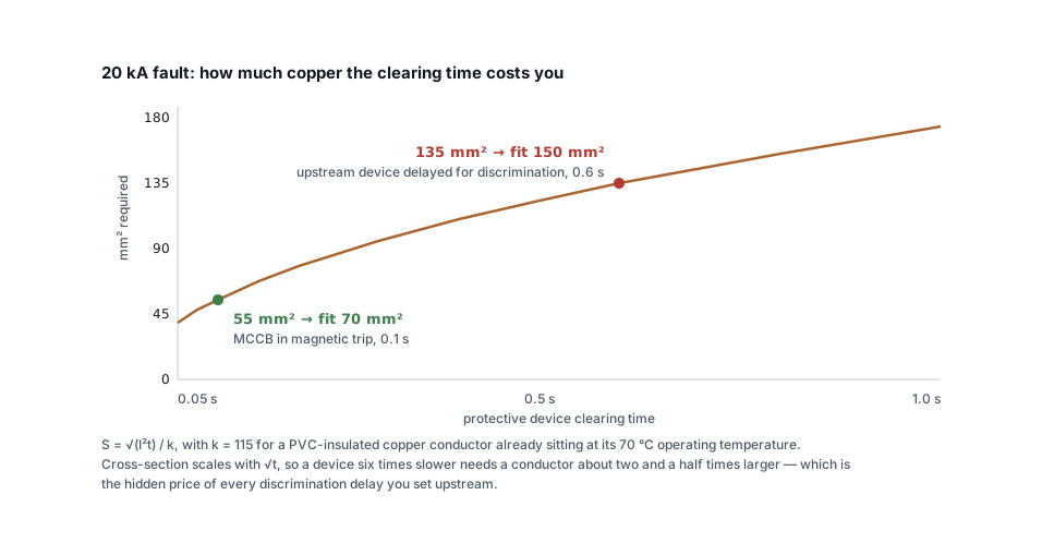
Worked through at 20 kA on a PVC-insulated copper cable:
Clearing in 0.1 s:
  S ≥ √(20,000² × 0.1) / 115 = 6,325 / 115 = 55.0 mm²   → fit 70 mm²

Clearing in 0.6 s:
  S ≥ √(20,000² × 0.6) / 115 = 15,492 / 115 = 134.7 mm² → fit 150 mm²
Two frame sizes of copper, bought entirely with time.
This is the hidden cost of discrimination. Every deliberate delay you set on an upstream device — so that the downstream one trips first and only the faulty circuit is lost — has to be paid for in the withstand rating of everything upstream of it. Discrimination is usually worth having. It is not free, and the cable schedule is where the bill arrives.
Get the time from the actual device curve at the actual fault current, not from a table of maximum permitted disconnection times. Those tables are about shock protection, which is a different requirement with a different purpose.
Where current-limiting devices change the picture
A current-limiting MCCB or an HRC fuse opens so fast that it cuts the fault before the first peak is reached. The cable never sees the prospective current at all.
For these, the calculation above is far too pessimistic. Use the device's published let-through energy — the I²t value in A²s from its datasheet — and check it directly against the cable:
k² S² ≥ let-through I²t
A 100 A current-limiting MCCB might let through 0.15 × 10⁶ A²s on a 20 kA
fault. For 70 mm² copper PVC, k²S² = 115² × 70² = 64.8 × 10⁶ — a very
comfortable margin. On high fault-level systems this is often the only
economical way to protect a cable, and it is why fuses persist on large feeders
long after breakers took over everywhere else.
Where the fault current comes from
You need a fault current at the point being protected, and it is not one number for the whole installation.
Start at the transformer: the transformer sizing calculator gives the terminal fault level from the kVA and impedance. Then remember that impedance accumulates down the system — every metre of cable reduces the fault current further from the source. The short circuit current calculator builds that up properly, adding the cable resistance and reactance to the transformer impedance and reporting the fault at the point you care about rather than at the terminals.
That gives two checks, not one:
- At the origin of the cable, where the fault current is highest. This is the case for conductor damage.
- At the far end, where the fault current is lowest. This matters because a fault there must still be large enough to operate the protective device quickly. A long, thin cable can produce a fault current so low that the breaker's magnetic element never picks up and the cable is protected only by the much slower thermal element — at which point the withstand calculation has to be redone at that much longer time, and it usually fails.
The second case is the one that catches people on long submains, and it is the argument for checking the earth fault loop impedance rather than assuming.
Cables in parallel
Where a feeder is made up of two or more cables per phase, the fault current divides between them — but only if they are genuinely identical. Same size, same length, same route, same installation method. Then each cable is checked against its own share, and the requirement per cable falls accordingly.
Depart from that in any way and the assumption collapses. A parallel set where one run is noticeably shorter has a lower impedance on that path, so it takes more than its share of both load and fault current. The short cable overheats while the long one loafs, and the withstand calculation you did on an equal split was never true. If the routes cannot be made equal, size every cable in the set for the worst-case share rather than the average.
Where this sits in the sequence
Short-circuit withstand is step six of the six-step sequence, and in that worked example — a 45 kW motor with a compliant 50 mm² by every other measure — it is the step that drove the answer to 70 mm². Current rating and volt drop both had margin. The fault check did not.
That is the pattern worth internalising: each step produces a minimum, and you install the largest. A cable schedule that never once got its answer from step six is a cable schedule where step six was not performed.
A short checklist
- Fault current from the transformer impedance, reduced for the route to this cable.
- Clearing time from the device curve at that current — including any discrimination delay.
- k from the phase conductor column, matched to the insulation.
- For current-limiting devices, use published let-through energy instead.
- Check the far end as well as the origin, and confirm the device still operates magnetically on a fault there.
- Take the largest size produced by all the checks, then confirm it still passes volt drop with the voltage drop calculator — a bigger cable never fails that, but the schedule should record the final size against every criterion.
Related articles
More on cable sizing.
 Cable sizing
Cable size for large loads: when to run cables in parallel
Above 300 mm², a bigger cable size stops paying. When to run cables in parallel, the six rules for equal sharing, and the overload no breaker can see.
10 min read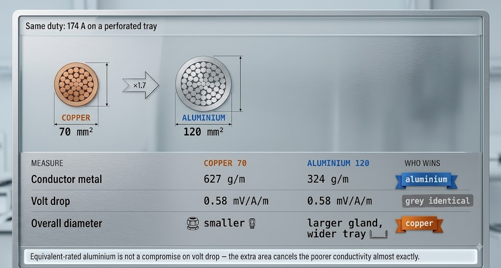 Cable sizing
Copper or aluminium: where aluminium stops being cheaper
Aluminium needs 1.6 times the cross-section for the same current — and still costs less per metre. The crossover, and the four places it goes wrong.
8 min read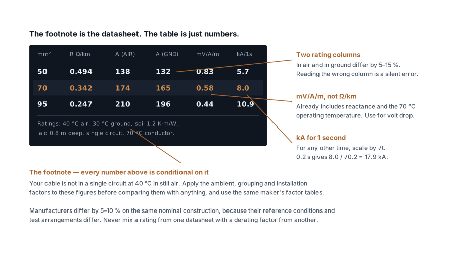 Cable sizing
How to read a cable datasheet without getting caught out
Reference conditions, two rating columns, mV/A/m versus ohms per km, one-second fault ratings and how to decode A2XFY — the fine print that decides the size.
7 min read Cable sizing
Cable derating factors: the complete table
Ambient, grouping and installation factors in one place, worked through — plus the four factors that are not in any table but still apply.
11 min read
Comments
Loading…