
Voltage drop limits: why lighting gets 3 % and power 5 %
What IS 732 actually permits, where the two limits come from, and why the same cable can pass for a motor and fail for a lighting board on the same site.
Two numbers get quoted on every Indian electrical drawing: 3 % for lighting, 5 % for power. They are correct, but they are quoted as though they were properties of the cable. They are not. They are properties of what sits at the end of it, and understanding why they differ is what lets you argue for the right one when a run is marginal.
This is where the voltage drop limits in IS 732 come from, how to apply them from the origin of the installation rather than from the nearest board, and the three situations where meeting them still leaves you with a problem.
What the limits actually say
IS 732 permits a voltage drop, between the origin of the installation and any point of utilisation, of:
| Circuit type | Limit | On a 415 V system | On a 230 V system |
|---|---|---|---|
| Lighting | 3 % | 12.45 V | 6.9 V |
| All other uses (power) | 5 % | 20.75 V | 11.5 V |
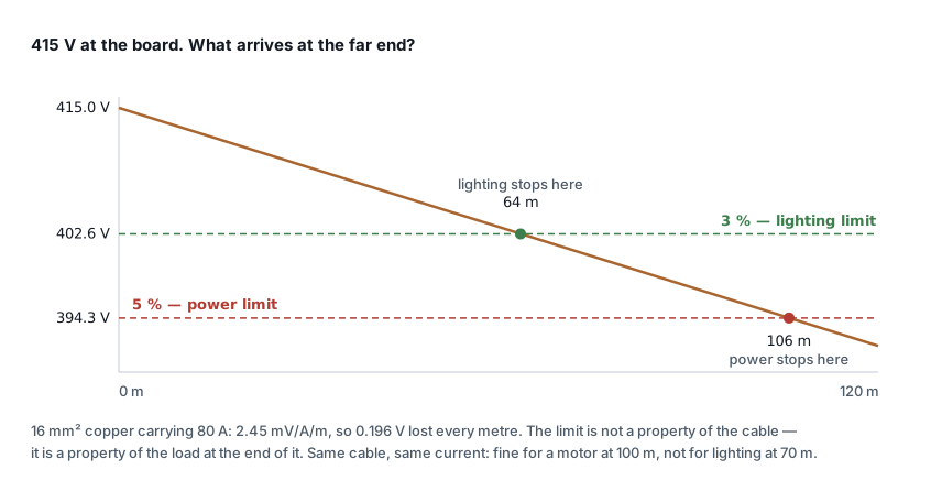
The words that matter are origin of the installation. The limit is not 5 % per cable. It is 5 % in total, from the incomer to the socket, added up across every cable in the chain: the submain to the distribution board, the final circuit from the board, and anything between.
This is the single most common misapplication. A submain that drops 3 % and a final circuit that drops 3 % have both individually "passed", and together they have failed. On any installation with more than one level of distribution, set a budget before you start — 2 % for the submain, 3 % for finals is a common split — and size to the budget rather than to the headline figure.
Why lighting gets the tighter limit
Not because lighting is more delicate, but because of what happens either side of the limit.
A motor tolerates a sag and then punishes you for it. Torque falls with the square of voltage — 10 % low is 19 % less torque — and to deliver the same mechanical power the motor draws more current, runs hotter and ages faster. But it keeps working, and nobody standing next to it can see anything wrong. The 5 % limit is set where that penalty is acceptable rather than where the motor stops.
Lighting shows you immediately. Discharge and fluorescent gear becomes unreliable at the bottom of its voltage range, and low voltage at the end of a long circuit is visible as a difference in output between one end of a corridor and the other. Filament and older halogen sources dim visibly at a few per cent. The tighter limit is a quality-of-installation limit, not a safety one.
Modern LED drivers complicate this. Most are constant-current with a wide input range — 140–270 V is typical — and genuinely do not care about a 5 % drop. That is an argument for relaxing the limit on a specific LED installation with the designer's justification, not for ignoring the standard by default. The 3 % figure also has to survive the next refit, when someone puts something else on that circuit.
Working it out
For a three-phase circuit, using the mV/A/m figure from the cable table:
Vd (volts) = mV/A/m × Ib × L / 1000
Vd (%)     = Vd / nominal voltage × 100
L is the one-way route length, not the loop length — the table figure already
accounts for the return path. Use the actual routed length including drops and
risers, not the straight-line distance on the layout. Cable routes are typically
20–30 % longer than they look on a plan.
Worked through for the run in the chart: 16 mm² copper, 2.45 mV/A/m, carrying 80 A.
Per metre:  2.45 × 80 / 1000       = 0.196 V/m
At 64 m:    0.196 × 64  = 12.5 V   = 3.02 %   ← lighting limit reached
At 106 m:   0.196 × 106 = 20.8 V   = 5.00 %   ← power limit reached
At 120 m:   0.196 × 120 = 23.5 V   = 5.67 %   ← fails either way
One cable, one current, three different verdicts depending on where you stop and what you connected. The voltage drop calculator does this against both limits at once.
When volt drop, not current, picks the cable
On short runs the current rating decides the size. Past a certain length volt drop takes over, and from then on the cable is bigger than it needs to be for heating reasons alone.
The crossover is closer than people expect. As a rough guide on 415 V:
| Design current | Volt drop starts governing beyond roughly |
|---|---|
| 20 A | 90 m |
| 50 A | 70 m |
| 100 A | 55 m |
| 200 A | 40 m |
Higher current means the crossover comes sooner, because volt drop scales with current while the tabulated rating does not scale as fast. On long runs feeding large loads — a pump house at the back of a plot, a tube well, a remote compressor shed — assume volt drop will govern and size for it first.
The cheapest fix is usually not more copper. It is moving the distribution board closer to the load and running the length at a higher voltage or a lower current. A 20 kW load at 100 m needs a lot of cable; the same load fed from a board 15 m away, with the length taken up by a lightly loaded submain, needs far less.
Three cases where 5 % is not enough
Motor starting. The limits above are steady-state. During a direct-on-line start the motor draws six to seven times full load current, and the drop is six to seven times as large. A run sitting at 4 % running will see 25 % or worse during a start — enough to drop out contactors on the same board and enough that the motor may not accelerate at all. For DOL circuits, check the drop at starting current, not just at running current. The usual working limit is 15 % transient at the motor terminals.
Long cable to a VFD. The drive rides through supply variation, so the input cable is rarely the problem. The output cable to the motor is, for entirely different reasons — reflected wave, dv/dt and charging current — and volt drop limits are not what governs it.
The utility's share. Your 5 % starts at your origin. The DISCOM has its own tolerance upstream, and IS 12360 permits ±6 % at the point of supply. If the incoming supply is already sitting 5 % low at peak, your compliant 5 % lands the far end 10 % below nominal. On sites with known weak supply, measure at the incomer at the worst hour before you design to the full allowance.
What to check before you sign it off
- Total drop from the origin, not per cable.
- Routed length, with drops and risers.
- The design current, including the 1.25 factor on motor circuits.
- The right limit for what is actually connected — and remember a mixed board gets the 3 % figure for its lighting ways.
- Starting conditions on DOL motor circuits.
- Whether volt drop has pushed the size above what the derated current rating required, in which case the cable is volt-drop governed and any change to the route matters more than a change to the load.
Size the cable end to end with the cable sizing calculator, which checks derated current capacity and volt drop together and tells you which of the two picked the size, or check an existing run against both limits with the voltage drop calculator.
Standards referenced
- IS 732 — Code of Practice for Electrical Wiring Installations. Bureau of Indian Standards
- IS 12360 — Voltage Bands for Electrical Installations Including Preferred Voltages and Frequency. Bureau of Indian Standards
Titles are given as commonly published. Check the current edition with the publisher before relying on a clause in professional work.
Related articles
More on cable sizing.
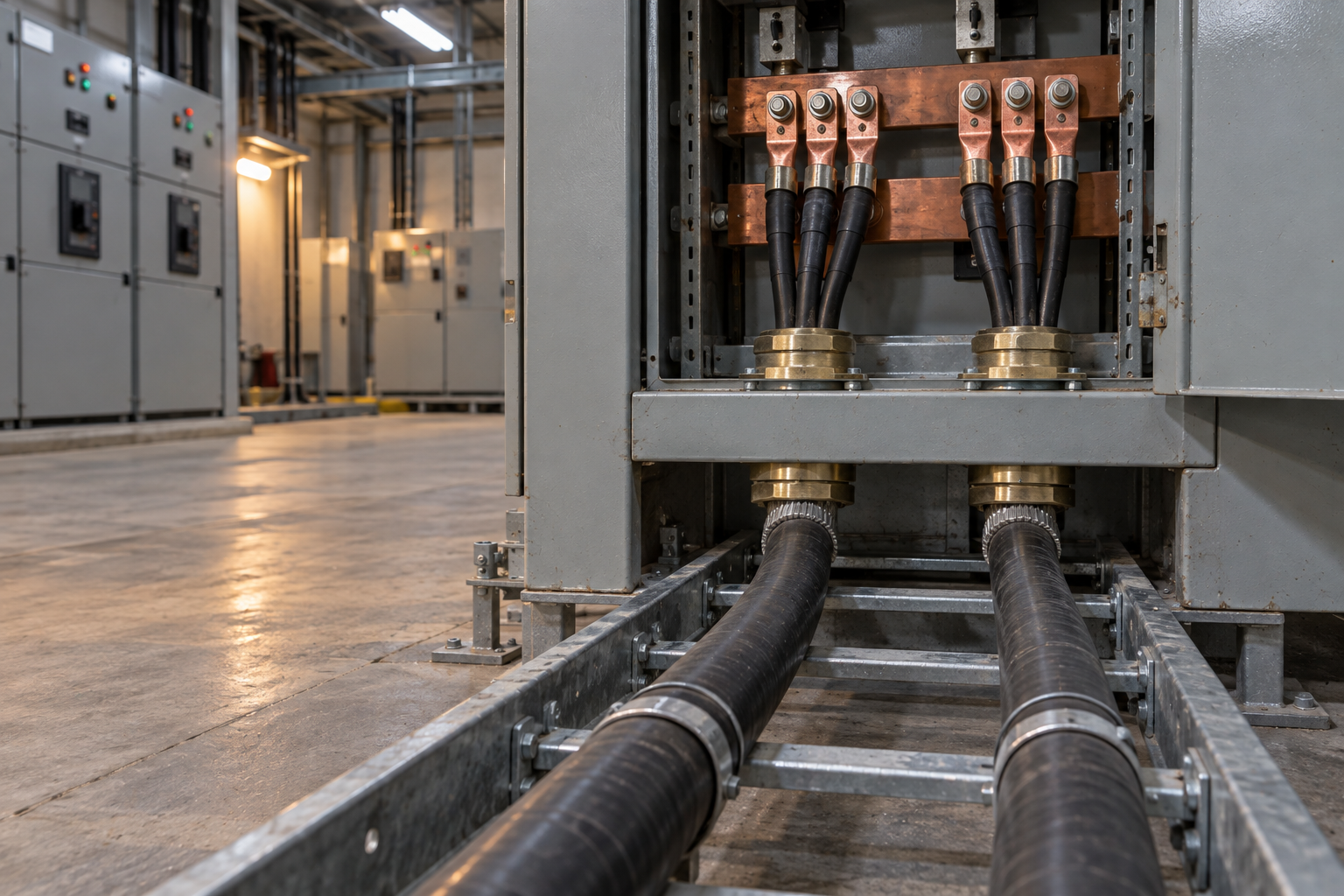 Cable sizing
Cable size for large loads: when to run cables in parallel
Above 300 mm², a bigger cable size stops paying. When to run cables in parallel, the six rules for equal sharing, and the overload no breaker can see.
10 min read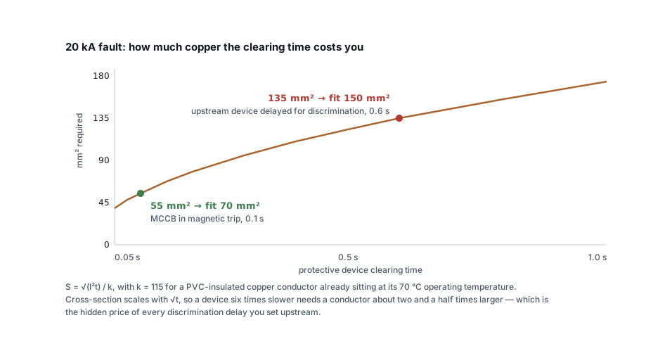 Cable sizing
Short-circuit withstand: the cable check everyone skips
A cable that passes current rating and volt drop can still fail under fault. The adiabatic check, the right k value, and why discrimination delays cost copper.
7 min read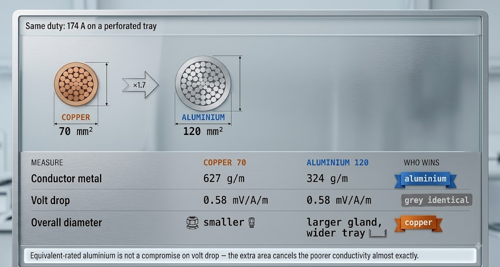 Cable sizing
Copper or aluminium: where aluminium stops being cheaper
Aluminium needs 1.6 times the cross-section for the same current — and still costs less per metre. The crossover, and the four places it goes wrong.
8 min read Cable sizing
How to read a cable datasheet without getting caught out
Reference conditions, two rating columns, mV/A/m versus ohms per km, one-second fault ratings and how to decode A2XFY — the fine print that decides the size.
7 min read
Comments
Loading…