
Cable derating factors: the complete table
Ambient, grouping and installation factors in one place, worked through — plus the four factors that are not in any table but still apply.
Every cable current rating you have ever read off a table was measured in a laboratory, on one cable, in still air, at a fixed ambient. Your cable is in a bunch of six, in a conduit, in a roof void that hits 55 °C in May. The tabulated figure is the starting point of the calculation, not the answer, and the gap between the two is bigger than most people expect — routinely more than half.
This is the complete set of cable derating factors, what each one is correcting for, and a worked example where three factors together push a circuit from 6 mm² to 16 mm².
The one equation
Derating factors multiply. They do not average and they do not get picked from whichever is worst:
Iz required = Ib / (Ca × Cg × Ci)
Ib— design current, the current the circuit actually carriesCa— ambient temperature correctionCg— grouping correctionCi— installation method correction
The multiplication is what catches people. Three factors that each look mild — 0.61 and 0.57 — combine to 0.348. A cable rated 70 A is a 24 A cable in that installation.
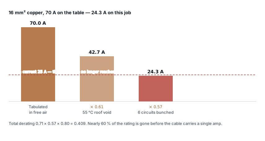
Ambient temperature
Rating tables are published against a reference ambient, and for cables in air that reference is 30 °C — IS 732:2019 adopts IEC 60364-5-52, and the major Indian cable catalogues quote their ratings the same way. Older parts of IS 3961 used 40 °C, which is why you still meet the figure; if you are working from a table on that basis, the factors below do not apply to it.
These are not looked up, they are derived. Current heats a conductor as
I²R, so temperature rise goes with the square of the current — which means
the current a cable can carry goes with the square root of the temperature
headroom it has left:
Ca = √( (θc − θa) / (θc − θref) )

θc   = conductor limit — 70 °C for PVC, 90 °C for XLPE
θa   = ambient at the cable
θref = 30 °C, the reference for cables in air
| Ambient | PVC (70 °C conductor) | XLPE (90 °C conductor) |
|---|---|---|
| 30 °C | 1.00 | 1.00 |
| 35 °C | 0.94 | 0.96 |
| 40 °C | 0.87 | 0.91 |
| 45 °C | 0.79 | 0.87 |
| 50 °C | 0.71 | 0.82 |
| 55 °C | 0.61 | 0.76 |
| 60 °C | 0.50 | 0.71 |
Every figure above comes straight out of that formula and matches the published
table in IEC 60364-5-52 to two decimal places, so you can check any of them in
one line rather than trusting a transcription. At 55 °C a PVC cable has 15 °C of
rise left where it was designed for 40 °C: √(15/40) = 0.61.
Two things worth noticing.
Above 30 °C the factors are penalties and below it they are bonuses — but only take the bonus if you are certain of the ambient for the life of the installation. An air-conditioned server room today can be an ordinary room in five years.
XLPE derates more gently than PVC, because it starts from a 90 °C conductor limit rather than 70 °C, so a given rise in ambient eats a smaller share of its headroom. That is one of the real arguments for XLPE in hot plant rooms, quite apart from its higher base rating.
The ambient that matters is the air immediately around the cable, not the room temperature and certainly not the outside temperature. A tray at high level under a metal roof can sit 15 °C above the floor of the same shed.
Grouping
Cables that run together heat each other. The factor depends on how many circuits are bunched and whether they touch.
| Circuits | Bunched in conduit or trunking | One layer, touching |
|---|---|---|
| 1 | 1.00 | 1.00 |
| 2 | 0.80 | 0.85 |
| 3 | 0.70 | 0.79 |
| 4 | 0.65 | 0.75 |
| 5 | 0.60 | 0.73 |
| 6 | 0.57 | 0.72 |
| 7 | 0.54 | 0.72 |
| 8 | 0.52 | 0.71 |
| 9 | 0.50 | 0.70 |
The left column is IEC 60364-5-52 Table B.52.17, which IS 732 adopts. Which column you are in matters more than the count. Six circuits bunched inside a conduit is 0.57; the same six spaced in one layer on a wall is 0.72 — a quarter more capacity for an arrangement that costs nothing but tray width.
Check which arrangement your table's column is for. These are for circuits in a single layer, touching — on a tray, a wall, or clipped to a surface. Circuits bunched inside a conduit or trunking cannot shed heat sideways and derate considerably harder; that is a different column in the standard, and using this one for an enclosed bunch will flatter the answer.
The first neighbour costs the most — 15 % for one extra circuit — and the curve flattens after about six. This has a practical consequence worth knowing: if you are already at eight circuits, adding two more is nearly free. If you are at one, adding a second is expensive.
Spacing changes everything. These factors are for cables touching. Space them by one cable diameter and the correction largely disappears; the standard gives separate, much gentler tables for spaced arrangements. On a tray with room to spare, spacing cables out is free capacity — it costs nothing but tray width and it is the cheapest derating fix available.
Count circuits, not cables. Three single-core cables forming one three-phase circuit are one circuit, not three.
Installation method
How the cable sheds heat to its surroundings:
| Method | Factor |
|---|---|
| Clipped in free air | 1.00 |
| On perforated tray | 0.95 |
| Buried direct in ground | 0.90 |
| In conduit or duct | 0.80 |
A simplification worth knowing about. IS 732 and IEC 60364 do not apply an
installation factor on top; they publish a separate current rating for each
reference method, and you read the column that matches how the cable is
actually run. The single multiplier above is the shortcut most Indian
catalogues print, and it is close enough for a first pass — but if your cable
table already gives a rating for the method you are using, take that figure
and leave Ci out rather than derating twice.
Conduit is the expensive one, and it is also the most common on small circuits. A cable in a conduit is in a small volume of still air inside an enclosure that is itself an insulator. Nothing about that arrangement helps it cool.
For buried cables there is more to it than a single factor. Soil thermal resistivity varies from about 0.8 K·m/W for damp clay to 2.5 or worse for dry sand, and the tabulated ratings assume around 1.2. Dry sandy ground can cost another 20 %. Depth of laying matters too — deeper is cooler in the short term but sheds heat more slowly, and beyond about 0.8 m the ratings start to fall again.
The factors that are not in the table
These four apply on real jobs and get missed because there is no obvious box to tick.
Thermal insulation. A cable buried in building insulation, or run through a sprayed-foam wall, cannot lose heat at all. For a cable surrounded by insulation for more than about 0.5 m, the standard applies a factor of 0.5. This is one of the few corrections that is more severe than everything above it, and it is almost never applied.
Direct sunlight. A black cable in Indian sun reaches 15–20 °C above ambient. If you have an outdoor run on a wall or an unshaded tray, correct as though the ambient were that much higher — because for that cable it is.
Harmonics. This one is growing. On a supply feeding VFDs, LED drivers or large numbers of switch-mode power supplies, the third harmonic and its multiples do not cancel in the neutral — they add. A neutral carrying more current than the lines is entirely possible, and where third harmonic content exceeds about 33 % the neutral becomes the sizing conductor. IEC 60364-5-52 handles it in three bands: below 15 % third harmonic, no correction; from 15 % to 33 %, apply 0.86 to the line current; above 33 %, size the cable on the neutral current instead of the line current. On a plant that is mostly VFDs, that last case is not exotic.
Enclosed in a panel. Cables inside an enclosure sit in the panel's internal ambient, which is typically 10–15 °C above the room. Apply the ambient factor for the panel, not the plant room.
Worked example: a lighting circuit in a roof void
A 25 A lighting and small-power circuit. The run goes through a roof void that reaches 55 °C in summer, in a conduit shared with five other circuits.
Without derating, the choice is easy. 6 mm² copper is rated 39 A, comfortably above 25 A. Two cores of 6 mm², job done.
Now apply the factors:
Ca (PVC at 55 °C)              = √(15/40) = 0.61
Cg (6 circuits, bunched)                  = 0.57

Total derating                 = 0.61 × 0.57 = 0.348

Iz required = 25 / 0.348 = 71.9 A
Two factors, not three. The conduit is not a separate multiplier — it is what put you in the bunched column of the grouping table, and it is also what decides which current-rating column you read. Apply a third factor for it and you have derated the same physical fact twice.
So the circuit needs a cable rated 71.9 A in the installation method actually being used. Read that from the column for conduit, not from the free-air column, and take the first size at or above it.
The number worth carrying away is the ratio: a 25 A circuit needing a 72 A cable. Derating did not trim the answer, it nearly tripled it — and none of that appears anywhere on the drawing that says "25 A lighting circuit".
Three sizes up, from a circuit that looked trivial. And the cost is not only the copper: 16 mm² will not terminate in the accessories a 6 mm² circuit was designed around, and it may not fit the conduit that caused the problem in the first place.
What to do when the answer is too big
Derating is not a tax you simply pay. Every factor is describing a physical problem, and most of them can be fixed more cheaply than by buying copper:
| Problem | Cheaper fix than upsizing |
|---|---|
| Grouping 0.57 | Space the cables one diameter apart, or split across two trays |
| Conduit 0.80 | Move to perforated tray — 0.95, and easier to add circuits later |
| Ambient 0.61 | Ventilate the roof void, or reroute below the ceiling |
| Everything at once | Split the load across two smaller circuits on different routes |
| PVC in a hot area | Specify XLPE — higher base rating and gentler ambient derating |
The reroute is usually the winner. A cable that leaves the hot zone entirely recovers its full rating for nothing but labour.
Two mistakes worth naming
Applying factors to the design current instead of the rating. The factors
correct the cable's capacity, not the load. Iz ≥ Ib / factors, never
Ib × factors. Getting this backwards makes the cable smaller instead of
bigger, and the arithmetic still looks plausible.
Stopping once the current is satisfied. A derated cable still has to pass the volt drop check and the short-circuit withstand check. Derating and volt drop pull in the same direction — both push the size up — so a long circuit in a hot bunch can be governed by either. Work through the whole sequence in how to size a cable correctly rather than stopping at the first satisfied condition.
The cable sizing calculator applies the ambient, grouping and installation factors together and shows the total derating alongside the selection, so you can see which factor is actually costing you the size.
One caution: these factors are representative values for PVC and XLPE armoured cable to common Indian practice. Manufacturers vary by 5–10 % for the same nominal construction. For anything being issued for construction, use the cable maker's own tables — and use the same maker's tables for both the rating and the factors, because they are derived together.
Standards referenced
- IS 732 — Code of Practice for Electrical Wiring Installations. Bureau of Indian Standards
- IEC 60364-5-52 — Low-voltage electrical installations — Part 5-52: Selection and erection of electrical equipment — Wiring systems. International Electrotechnical Commission
Titles are given as commonly published. Check the current edition with the publisher before relying on a clause in professional work.
Related articles
More on cable sizing.
 Cable sizing
Cable size for large loads: when to run cables in parallel
Above 300 mm², a bigger cable size stops paying. When to run cables in parallel, the six rules for equal sharing, and the overload no breaker can see.
10 min read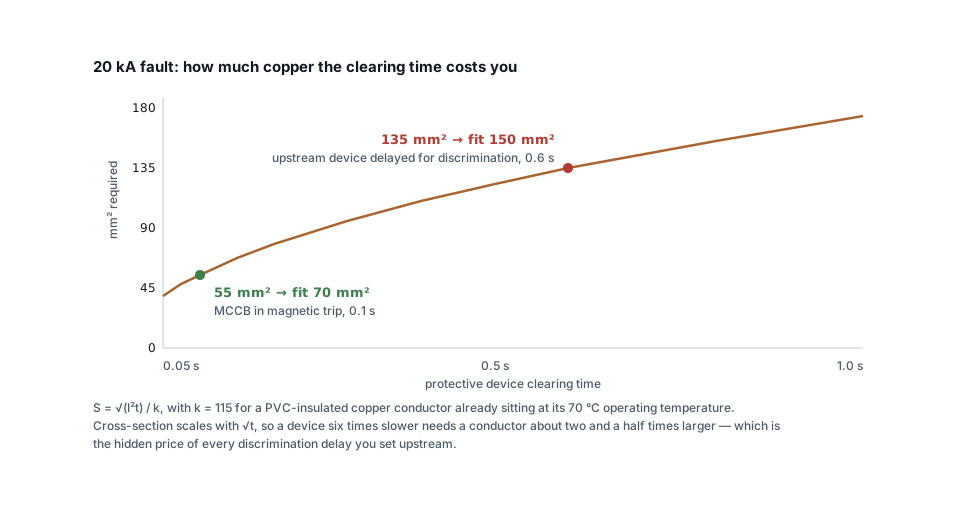 Cable sizing
Short-circuit withstand: the cable check everyone skips
A cable that passes current rating and volt drop can still fail under fault. The adiabatic check, the right k value, and why discrimination delays cost copper.
7 min read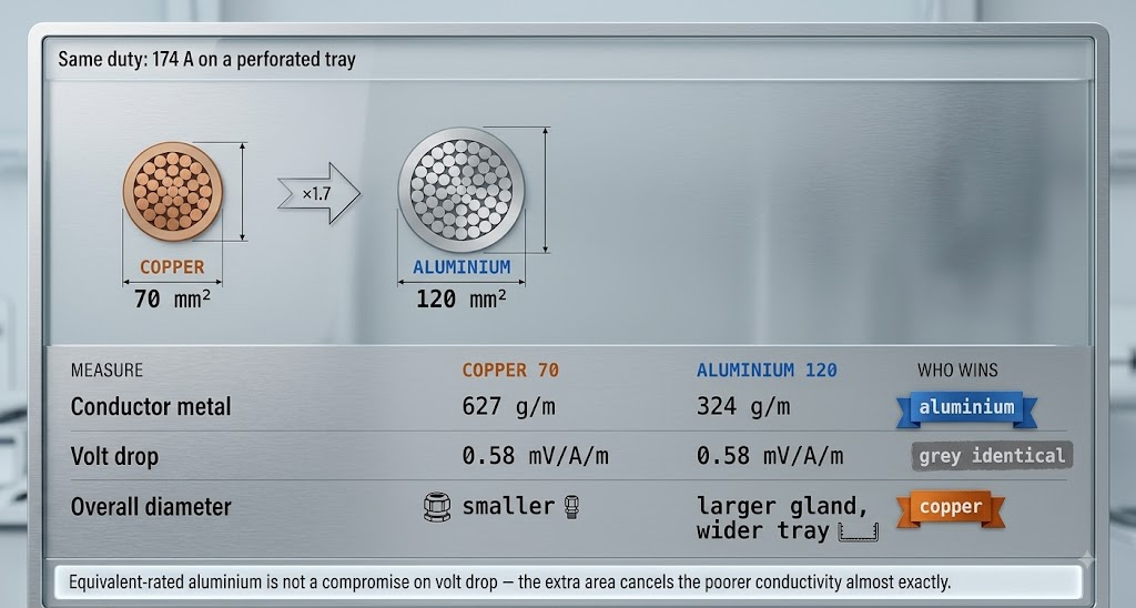 Cable sizing
Copper or aluminium: where aluminium stops being cheaper
Aluminium needs 1.6 times the cross-section for the same current — and still costs less per metre. The crossover, and the four places it goes wrong.
8 min read Cable sizing
How to read a cable datasheet without getting caught out
Reference conditions, two rating columns, mV/A/m versus ohms per km, one-second fault ratings and how to decode A2XFY — the fine print that decides the size.
7 min read
Comments
Loading…