
MCB, MCCB, ACB and RCCB: what each protects, and where
The four devices compared on rating, breaking capacity and adjustability — plus trip curves, Icu versus Ics, and choosing an RCD type for VFD circuits.
Four devices turn up on every distribution drawing, and the differences between them are usually explained as a matter of size — MCB small, MCCB medium, ACB large. That is true and it is not the useful distinction. They differ in what they can see, how far they can be adjusted, and how much fault current they can break, and those three properties decide where each one belongs.
The RCCB is not on the same list at all. It protects against something the other three cannot detect.
The short version
| MCB | MCCB | ACB | RCCB | |
|---|---|---|---|---|
| Typical range | 0.5–125 A | 16–1600 A | 630–6300 A | 25–125 A |
| Breaking capacity | 6–10 kA | 25–70 kA | 50–150 kA | none of its own |
| Detects overload | Yes, fixed | Yes, adjustable | Yes, adjustable | No |
| Detects short circuit | Yes, fixed | Yes, adjustable | Yes, adjustable | No |
| Detects earth leakage | No | Optional add-on | Yes, in the trip unit | Yes, its only job |
| Adjustable settings | None | Thermal, often magnetic | Everything, plus delays | Sensitivity is fixed |
| Maintainable | Replace | Replace | Serviceable, drawout | Replace |
| Where it belongs | Final circuits | Submains | Incomers, main bus | Wherever people are |
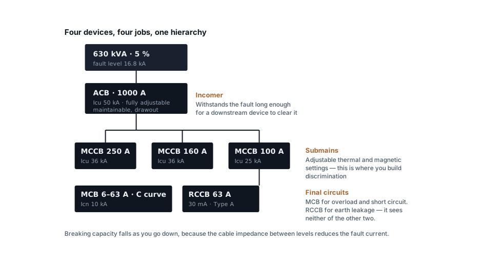
The one that is different
An MCB, MCCB and ACB all measure current flowing through them, and they trip when there is too much of it. That protects the cable and the equipment. It does essentially nothing for a person touching a live part.
Current flowing through someone to earth is a small current — 30 mA can be lethal, and a 32 A MCB will not notice 30 mA any more than it notices a light bulb switching on. An RCCB compares the current going out with the current coming back. If they differ, current is leaving the circuit somewhere it should not be, and it trips.
| Sensitivity | Purpose |
|---|---|
| 10 mA | Very high risk — medical, some laboratory |
| 30 mA | Protection of people. The figure for socket circuits and anywhere with human contact |
| 100 mA | Fire protection, some equipment protection |
| 300 mA | Fire protection on submains, or upstream of 30 mA devices for discrimination |
An RCCB has no overcurrent protection of its own. It must always sit behind an MCB or MCCB, sized so the RCCB's own current rating is never exceeded. An RCBO combines the two functions in one module, which costs more per way and means a leakage fault trips only the affected circuit — usually the better arrangement on anything the user cares about.
RCD types: the mistake that VFDs cause
This one is missed constantly, and it turns a safety device into an ornament.
| Type | Detects | Use for |
|---|---|---|
| AC | Sinusoidal AC leakage only | Simple resistive and inductive loads |
| A | AC plus pulsating DC | Anything with electronics — the sensible default today |
| F | Type A plus mixed frequencies | Single-phase VFD loads, washing machines |
| B | Type A/F plus smooth DC | Three-phase VFDs, EV chargers, solar inverters |
The failure mode is specific and dangerous. A fault downstream of a rectifier can produce leakage with a DC component, and DC leakage can saturate the core of a Type AC device so that it no longer detects the AC leakage it was fitted for. The device does not fail obviously — it stops working while looking perfectly healthy.
If the circuit has a VFD, an EV charger or a solar inverter on it, the RCD must be Type B (or Type F for single-phase drives). Type AC on such a circuit is a false sense of protection.
Trip curves
The trip curve says how fast the magnetic element operates as a multiple of the rated current:
| Curve | Trips magnetically at | For |
|---|---|---|
| B | 3–5 × In | Resistive loads, long cable runs, domestic |
| C | 5–10 × In | The general purpose choice — mixed loads, small motors |
| D | 10–20 × In | Transformers, motors, anything with high inrush |
A B-curve device on a motor circuit trips on every start. A D-curve device on a lighting circuit at the end of a long run may not trip on a genuine fault at all, because the fault current at that distance never reaches ten times the rating. That second failure is the more dangerous one, and it is why long final circuits sometimes need a B curve or an earth fault loop impedance check rather than an assumption.
For motors specifically, the right answer is usually not an MCB at all but an MPCB — a motor protection circuit breaker with an adjustable thermal element set to the motor's full load current and a fixed magnetic element around 13 × In that lets the starting inrush pass. The motor starter calculator picks one from the motor rating.
Icu, Ics and Icn — three breaking capacities
Datasheets quote more than one, and the difference matters:
- Icu — ultimate breaking capacity. The device will interrupt this fault once, safely. It may not be usable afterwards.
- Ics — service breaking capacity. It will interrupt this fault and remain fit for service. Usually quoted as a percentage of Icu: 50 %, 75 % or 100 %.
- Icn — rated breaking capacity for MCBs to IS/IEC 60898, the domestic and similar standard. Typically 6 kA or 10 kA.
Specifying on Icu alone means accepting that after a serious fault the device is scrap and possibly no longer protecting anything. On main incomers and anywhere downtime is expensive, specify Ics = 100 % of Icu.
Get the fault level from the transformer with the transformer sizing calculator, and remember it falls as you move down the system — which is why 10 kA MCBs are acceptable at a final distribution board fed by a long submain, and would not be acceptable on the main bus.
Discrimination, and the cheat that goes with it
Discrimination means a fault takes out only the device closest to it, leaving the rest of the installation running. It is built with the adjustable settings on MCCBs and ACBs: current thresholds that step up going upstream, and short time delays on the upstream devices so the downstream one gets the first chance to clear.
Those delays are not free. Every one of them extends the time the fault current flows, and the cable short-circuit withstand calculation scales with √t. A 0.6 s delay upstream can push a cable up two sizes.
Cascading (or back-up protection) is the related trick: an upstream current-limiting device is allowed to help a downstream one, so the downstream device can be specified below the prospective fault level at its position. It is cheaper, and it is only valid for tested combinations published by the manufacturer — you cannot derive it yourself, and you cannot mix brands.
Choosing, in order
The MCB and MCCB sizing calculator runs the sequence
below for a given circuit — rating, curve, breaking capacity and the
Ib ≤ In ≤ Iz check against your derated cable, with the panel-ambient
correction applied.
- Fault level at this point in the system — that sets the minimum breaking capacity, and Ics rather than Icu where continuity matters.
- Load current and the cable it protects — the device rating must sit between
the design current and the derated cable capacity,
Ib ≤ In ≤ Iz, which is step four of sizing a cable correctly. - Inrush behaviour of the load — which sets the curve, or sends you to an MPCB.
- Whether anyone can touch it — which decides the RCD, and its sensitivity.
- What electronics are downstream — which decides the RCD type.
- Whether a fault here should take out anything else — which decides how much adjustability you need to pay for.
Standards referenced
- IEC 60898 — Electrical accessories — Circuit-breakers for overcurrent protection for household and similar installations. International Electrotechnical Commission
Titles are given as commonly published. Check the current edition with the publisher before relying on a clause in professional work.
Related articles
More on panels, protection & earthing.
 Panels, protection & earthing
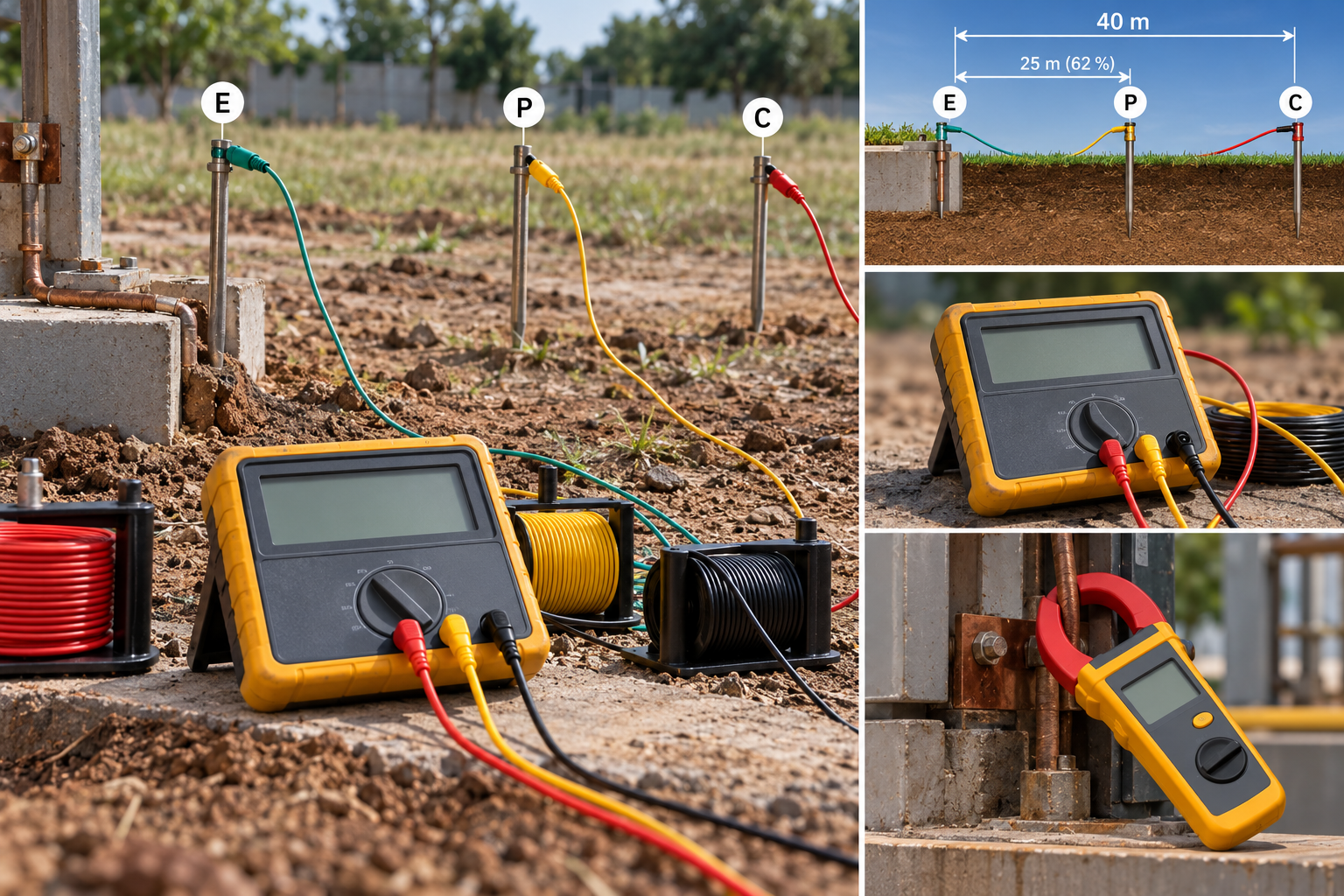
Earth resistance testing: the 62 % rule, and when the clamp-on lies
Fall-of-potential done properly, the three-position check that proves it, IS 3043 limits by application, and when a clamp-on tester measures nothing.
8 min read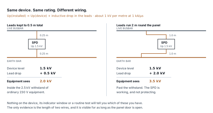 Panels, protection & earthing
SPD installation: the two wires that decide
An SPD with 2 m of lead passes more than twice the voltage it should. Lead length, Uc and type selection, and how to check a panel you did not build.
7 min read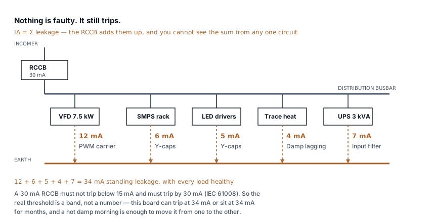 Panels, protection & earthing
RCCB keeps tripping: how to find the leakage
Healthy loads leak. Six of them on one board can trip a 30 mA RCCB with nothing faulty anywhere. How to measure the standing leakage and what to change.
8 min read Panels, protection & earthing
Types of earthing: plate, pipe, rod and chemical compared
Plate, pipe, rod and chemical earthing all obey one formula. What separates them is soil resistivity, depth and who maintains them — not the electrode material.
7 min read
Comments
Loading…