
Power factor still poor after fitting capacitors: why
The bank is installed, the contactors click, and the bill has not moved. Six causes, ranked, and the one clamp-meter test that finds most of them.
An APFC panel that has stopped working does not announce it. The controller display is lit, the contactors still click in and out on schedule, the indicator lamps are on — and the power factor on the bill is exactly where it was before you spent the money.
This is one of the most under-diagnosed installations in an industrial plant, because everything about it looks like it is running. Here is what is usually wrong, in the order it is usually wrong, and the one measurement that finds most of it.
Start here: clamp each step
Before theorising, measure. With the plant loaded and the controller switching, put a clamp meter on each capacitor step in turn and compare the current against what that step should draw:
I = kVAr × 1000 / (√3 × V)
A 25 kVAr step at 415 V should pull about 35 A. What you find tells you almost everything:
- Zero current on a step the controller says is on — the step has failed open, or its contactor or fuse has gone.
- Noticeably below the calculated figure — the capacitors have lost capacitance with age. A step down 20 % is still switching and still counted by the controller, and it is delivering four fifths of what it promises.
- Every step correct, power factor still poor — the problem is the controller or its CT, not the capacitors.
Ten minutes with a clamp meter separates three of the six causes below.
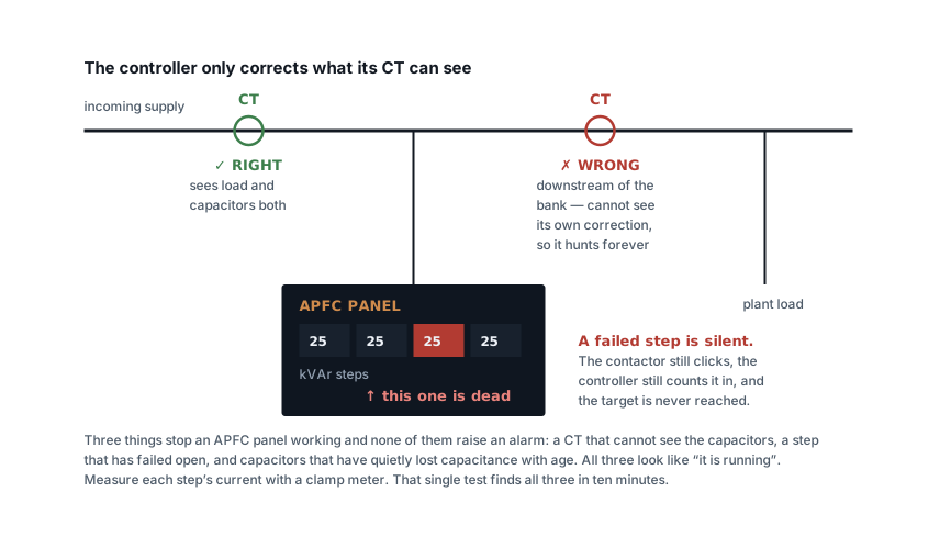
1. The CT is in the wrong place
The commonest single cause, and the most frustrating, because the panel was probably built correctly and the CT was fitted by somebody else.
The controller's CT must see both the load and the capacitors — which means it belongs on the incomer, upstream of the point where the bank connects. Put it downstream of the bank and the controller cannot see the effect of its own correction: it switches a step in, sees no change, switches another in, and hunts indefinitely. Put it on the wrong feeder entirely and it corrects for a load that is not the one being billed.
Reversed CT polarity produces the same class of nonsense. If the controller displays a leading power factor while the plant is obviously inductive, check polarity before anything else.
2. A step has failed, silently
Capacitors fail open. When one does, the contactor still operates, the controller still believes it has switched in 25 kVAr, and nothing indicates otherwise. On a six-step panel losing two steps, the bank delivers two thirds of its rating and the controller has no idea.
This is why the clamp test matters, and why an annual capacitance check on each step is a ten-minute job worth scheduling. Fuses are worth checking at the same time — an HRC fuse that has cleared looks identical to one that has not.
3. The capacitors have aged
Capacitors lose capacitance over their life, and heat accelerates it sharply — life roughly halves for every 7–10 °C above the rated temperature. A bank in an unventilated corner of a hot plant room can be delivering meaningfully less than its nameplate after three or four years while appearing perfectly healthy.
The symptom is a power factor that has drifted down gradually rather than dropped. If the bill shows a slow decline over two years, this is the likely cause, and no amount of controller adjustment will fix it.
4. C/k is wrong, so the controller hunts
Every controller needs to know how much current one step represents as seen through the incomer CT:
C/k = (step kVAr × 1000) / (√3 × line voltage × CT ratio)
Set it too high and the controller cannot detect the effect of its smallest step, so it switches in, sees nothing, and switches more. Set it too low and it becomes over-sensitive and does the same. Either way you get contactors cycling, capacitors wearing out early, and a power factor that never settles.
If the panel is audibly switching more than a few times an hour, suspect C/k before suspecting the capacitors.
5. The bank is too small, or too coarse
Two different problems that look alike on a bill.
Too small is arithmetic — run your measured load and target through the power factor calculator and compare with what is installed. Plants grow; a bank sized eight years ago for a smaller load will never reach the target now.
Too coarse is about steps rather than total. The controller only switches whole steps and will not overcorrect, so the residual reactive power is always somewhere between zero and one step. A 100 kVAr bank in two steps of 50 leaves up to 50 kVAr uncorrected at any moment. The total can be right and the result still poor — the fix is more, smaller steps, covered in APFC panels.
6. Harmonics are destroying the bank
If capacitors are failing repeatedly, fuses are blowing for no visible reason, or the bank runs hot, the problem is not power factor at all. Capacitors are a low impedance to high frequencies, and a plain bank on a supply with significant drive or rectifier load can resonate with the system inductance and amplify a harmonic that was previously tolerable.
Untreated, it destroys the capacitors — which then presents as cause 2 or 3, repeatedly, no matter how many times they are replaced. The fix is detuned reactors, typically 7 %, with capacitors rated for the higher voltage the reactors impose. Measure the distortion first; the harmonic loss calculator converts a spectrum into what it is costing you.
When it works on mains and not on the generator
A separate case worth knowing. On a lightly loaded generator, a fixed or slow-switching bank drives the power factor leading, the AVR hunts, and voltage becomes unstable. Some controllers respond by giving up entirely.
The bank should be interlocked to the changeover, or told which source is live so it can use a different target. This is a two-wire job that gets forgotten on almost every retrofit.
The display and the bill measure different things
One more reason a panel can be working and the bill still disappoints: they are not measuring the same quantity over the same period.
The controller shows instantaneous power factor, right now, at its CT. The utility bills an average over the whole billing period — usually computed from total kWh and kVArh, so every hour counts, including the ones when production was stopped.
That gap produces a specific and common complaint: the panel reads 0.98 all day, the bill says 0.91. The usual explanations are the hours nobody watches. Overnight, the plant load collapses but the transformer is still energised and drawing magnetising current, and a bank that has switched all its steps out is correcting nothing. Weekends do the same thing for two days at a stretch.
If the daytime figure is good and the monthly average is not, the fix is not more kVAr. It is a small fixed step left permanently in to cover the base magnetising load, or leaving one step enabled overnight — which is exactly what the "fixed compensation on the base load, switched steps on the rest" arrangement exists to do.
The order to work through
- Clamp every step. Compare against
kVAr × 1000 / (√3 × V). - Find the controller CT. Upstream of the bank, on the right feeder, correct polarity.
- Check C/k against the actual step size and CT ratio.
- Compare installed kVAr against a fresh calculation using measured load.
- Count the steps — is the smallest step 5–10 % of the total?
- Measure harmonics if capacitors keep failing.
- Check the target setting. 0.95–0.98, not unity — and confirm the tariff does not penalise leading power factor.
Reconcile against the bill afterwards, not against the controller display. The display shows what the CT sees; the bill shows what you are paying for, and those are the same number only when everything above is right.
Related articles
More on troubleshooting.
 Troubleshooting
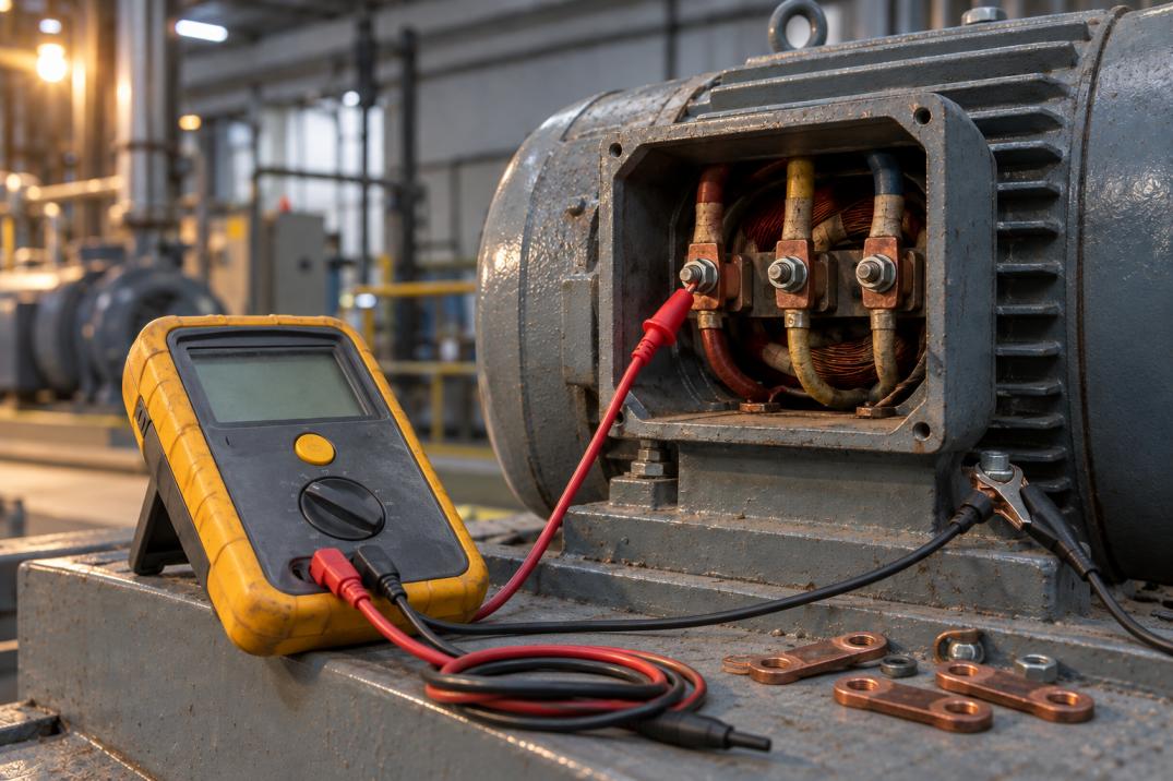
Insulation resistance test values: what passes, and when to reject
What a megger reading means: IS 732 and IEEE 43 limits, temperature correction, polarisation index, and the three things that fake a failure.
13 min read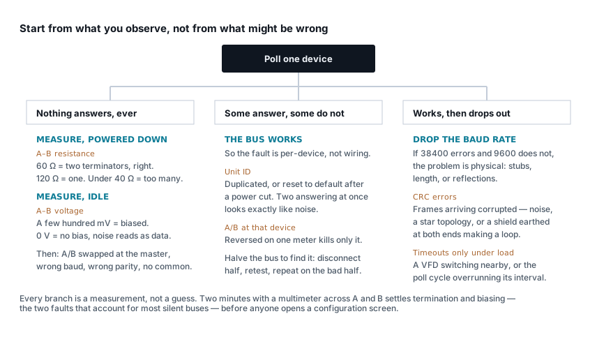 Troubleshooting
Modbus RTU not responding: a diagnostic sequence
Timeouts, CRC errors and silent devices, worked from what you can observe. Two minutes with a multimeter settles the two commonest causes.
7 min read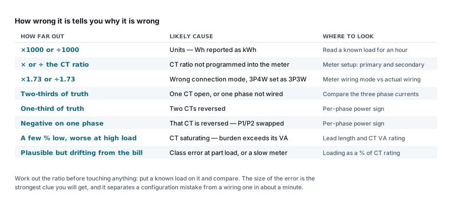 Troubleshooting
Energy meter showing wrong readings: a checklist
Work out how wrong it is first — the size of the error names the cause. Ratio errors, reversed CTs, saturation and the ones that look plausible.
7 min read Troubleshooting
MCCB keeps tripping: how to find out why
Time the trip first — it halves the search. Then work through overload, short circuit, earth fault and the causes that are not faults at all.
7 min read
Comments
Loading…