
CT ratio and burden: picking a CT that reads correctly
Why lead resistance dominates the burden on a 5 A secondary, what the S in class 0.5S buys you, and how an oversized ratio quietly loses accuracy at part load.
A current transformer is chosen on the ratio, and then everything else is left to whoever is ordering. That is how a submetering system ends up reading 4 % low, or reading beautifully at full load and hopelessly at night, with nothing visibly wrong anywhere.
The ratio is the easy part. The burden and the accuracy class are what decide whether the number the meter reports is true.
Burden is a budget, and the cable usually spends it
A CT is a current source. It will push its secondary current through whatever impedance you connect, developing whatever voltage that takes — up to the point where the core saturates and it simply cannot. Burden is the total impedance in that secondary loop, expressed in VA at rated secondary current.
Three things spend the budget:
- The meter or instrument.
- The resistance of the leads, there and back.
- Terminals, links and test blocks.
Worked through for a 200/5 CT feeding an electronic meter 10 m away on 2.5 mm² copper:
Lead loop      = 20 m of 2.5 mm² ≈ 0.148 Ω
Lead burden    = I²R = 5² × 0.148 = 3.70 VA
Electronic meter                  = 0.50 VA
Terminals and test block          = 0.50 VA
                                    ─────────
Total                             = 4.70 VA  → specify 7.5 VA
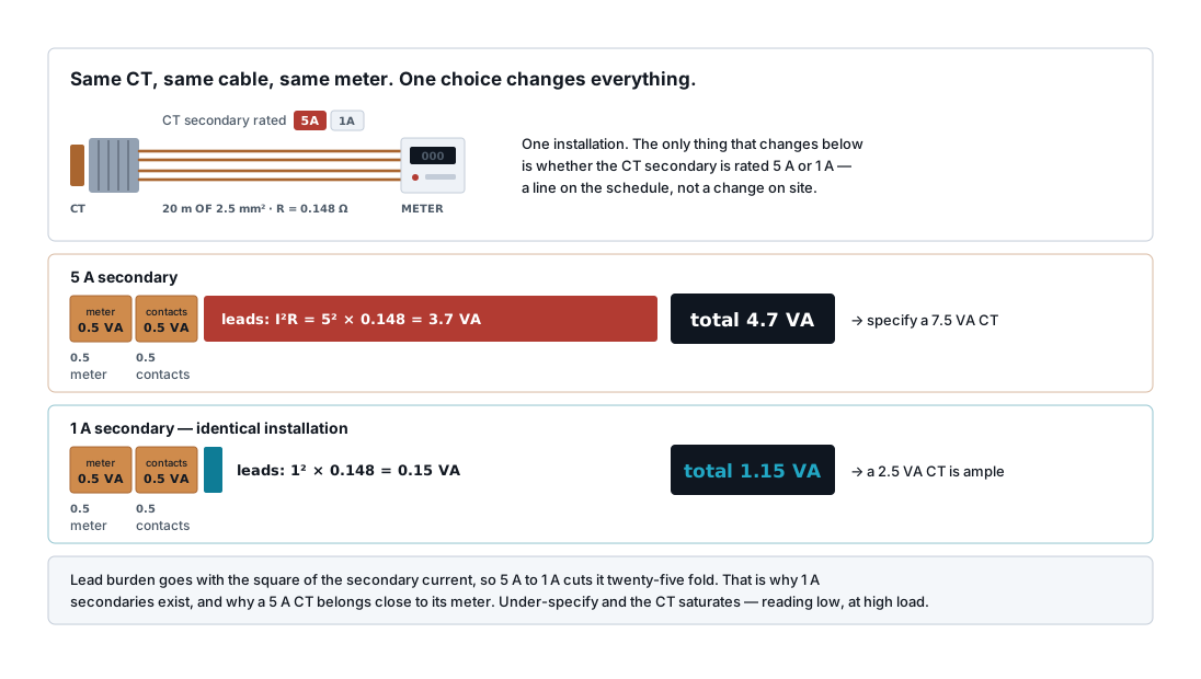
The meter is almost irrelevant. Modern electronic meters draw a few tenths of a VA; the old moving-iron instruments that made 5 VA meters normal are long gone. What is left is cable, and cable burden goes with the square of the secondary current.
Which is the entire argument for a 1 A secondary. Same cable, same meter, same distance:
Lead burden at 1 A = 1² × 0.148 = 0.15 VA
Total              = 1.15 VA  → a 2.5 VA CT is ample
Twenty-five times less. Use 5 A secondaries where the CT is close to the meter, and 1 A wherever the run is long. Above about 15 m, 1 A is usually the right answer, and above 30 m a 5 A secondary needs an uncomfortably fat cable to work at all.
What happens when you get it wrong
Under-burdened — a 15 VA CT operating at 2 VA — is harmless. A CT does not mind an easy life.
Over-burdened is the problem. The CT cannot develop the voltage needed to drive its rated current through the impedance, so the core saturates. Output falls below what the ratio promises and the meter reads low. Crucially it reads low in proportion to current, so the error grows as load rises — the readings are worst exactly when the energy matters most, and they look plausible at every point.
Nothing alarms. Nothing trips. You find out when someone reconciles submeter totals against the main meter and finds several per cent missing.
Accuracy class, and what the S means
| Class | Accuracy | Use |
|---|---|---|
| 0.2S | ±0.2 % | Revenue metering, HT connections |
| 0.5S | ±0.5 % | Sub-billing, tenant metering, energy management |
| 1.0 | ±1.0 % | Indication, general monitoring |
| 3.0 | ±3.0 % | Ammeters only |
| 5P10, 10P20 | Protection classes | Relays — not for metering |
The S matters more than most specifications acknowledge. A plain class 0.5 CT holds its accuracy from 20 % to 120 % of rated current. A class 0.5S CT holds it from 1 % to 120 %.
For energy monitoring that difference is the whole job. A plant that runs at 15 % load overnight is outside a plain 0.5 CT's specified range for a third of every day, and those hours quietly accumulate error into the daily total. If you are metering to allocate cost or to find savings, specify 0.5S.
Protection CTs are a different device. 5P10 means 5 % accuracy at 10 times rated current — they are designed to stay linear during a fault, and they are deliberately inaccurate at normal load. Never use a protection core for metering. Where a CT has multiple cores, use the metering core for the meter and the protection core for the relay, and label them, because a CT with its cores swapped produces both a bad energy reading and unreliable protection.
Do not oversize the ratio
The commonest field mistake, and it comes from good intentions: someone fits a 1000/5 CT on a circuit that draws 150 A "for future expansion".
That CT now operates at 15 % of rating. On a plain class 0.5 core, 15 % is below the specified range and the accuracy is undefined. Even a 0.5S core is working near the bottom of its range, and the secondary current at 0.75 A is small enough that noise and terminal resistance become significant.
Choose the ratio so normal load sits between 40 % and 100 % of the primary rating. If you are working from a kW figure rather than a measured current, convert it first with the three-phase current calculator — and use the running current, not the connected load, or you will oversize the CT for exactly the reason above. For a 150 A circuit that is a 200/5, not a 1000/5. If the load will genuinely grow later, change the CT later — a CT is a cheap component, and the years of wrong readings in between are not.
The related figure is the instrument security factor (FS or ISF), usually FS5 or FS10. It says the CT saturates at 5 or 10 times rated current, which protects the connected meter during a fault. That is a feature on a metering CT and a defect on a protection CT — another reason the two are not interchangeable.
Wiring a CT without causing damage
Never open-circuit an energised CT secondary. With no burden to drive, the core drives towards saturation and develops a very high voltage across the open terminals — hundreds or thousands of volts, capable of killing someone and of destroying the CT's insulation. Before disconnecting a meter on a live circuit, short the CT secondary first, which is what the shorting links on a test block are for.
Then get the polarity right. P1/P2 on the primary, S1/S2 on the secondary. A reversed CT shows negative power on that phase, and on a three-phase meter the total can look almost credible — low by roughly a third rather than obviously wrong. Check each phase individually against a clamp meter at commissioning, not just the total.
Earth the secondary at one point only, normally S2 at the meter end. Two earths make a loop and a path for circulating current.
Types, briefly
| Type | Notes |
|---|---|
| Solid core (ring) | Cheapest and most accurate. Needs the cable disconnected to fit |
| Split core | Clips around a live cable — retrofits, submetering. Slightly less accurate; the mating faces must be clean and fully closed |
| Rogowski coil | Flexible, no saturation, very wide range. Outputs a voltage, needs an integrator, and the meter must accept it |
| Wound primary | Small primary currents, where a bar CT would be inaccurate |
Split-core CTs deserve one warning: a gapped or dirty mating face adds reluctance and the CT reads low. If a retrofitted split core reads a few per cent below a clamp meter, open it and clean the faces before doubting anything else.
A specification that will read correctly
- Ratio such that normal load is 40–100 % of primary rating.
- Class 0.5S for anything used to allocate or analyse energy.
- Burden calculated — meter plus lead loop plus terminals — then round up to the next standard VA.
- 1 A secondary if the run exceeds about 15 m.
- FS5 or FS10 on metering cores.
- Shorting-type test block at the meter.
- Polarity verified per phase at commissioning against a clamp meter.
Once the CT is right, the rest of the chain is the meter and the bus — see choosing an energy meter for IoT and Modbus RTU on energy meters. A perfectly polled register is still a wrong number if the CT feeding it was saturating.
Related articles
More on metering & iot.
 Metering & IoT
PROFIBUS and PROFINET: how each is wired, and what breaks
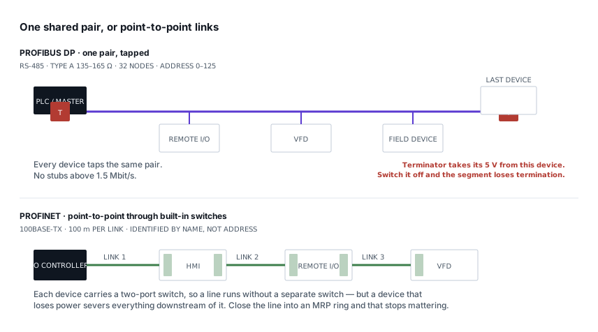
Purple cable at 150 Ω against green Ethernet, powered termination against none, device addresses against device names — and the fault each design invites.
8 min read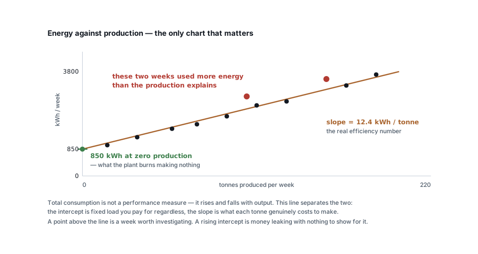 Metering & IoT
Turning meter data into savings: baselines, KPIs and alerts
Why total kWh is a useless measure, how to build an energy baseline against production, and the four analyses that actually find money in metering data.
6 min read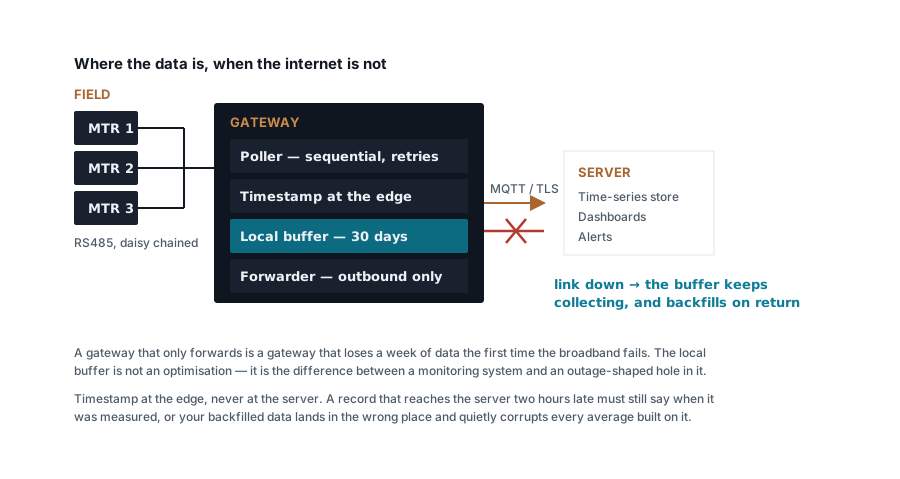 Metering & IoT
Building a Modbus energy monitoring gateway that stays up
Polling design, store-and-forward, timestamping at the edge, SD card wear and the naming convention you cannot change later — a field-grade gateway.
7 min read Metering & IoT
MQTT, Modbus TCP or HTTP: moving meter data to a server
Poll versus publish, what each protocol costs in bandwidth and firewall holes, how to design topics and payloads, and where each one genuinely belongs.
7 min read
Comments
Loading…