
RS485 wiring for Modbus: topology, termination, shields
Daisy chain not star, 120 Ω at both ends only, one earth on the shield, and the third wire everybody omits — the physical layer that decides if polling works.
Most Modbus problems are blamed on software and caused by wiring. The characteristic symptom is a bus that works perfectly during commissioning, with two meters connected on a bench, and then develops intermittent timeouts once twenty devices are installed across a building.
RS485 is extremely tolerant — right up until it is not, and the point where it stops being tolerant depends on length, baud rate and device count together. A bus that is marginal will pass every test you run on the day and fail on a Tuesday in month three.
Here is what the physical layer actually requires.
Why RS485 works at all
RS485 sends data as a voltage difference between two wires rather than as a voltage relative to earth. Interference from a nearby motor cable couples into both wires almost equally, so it moves them both together and the difference between them is untouched. That is why a two-wire pair carries reliable data a kilometre through an electrically filthy factory.
Everything below is about preserving that property.
Daisy chain. Never star.
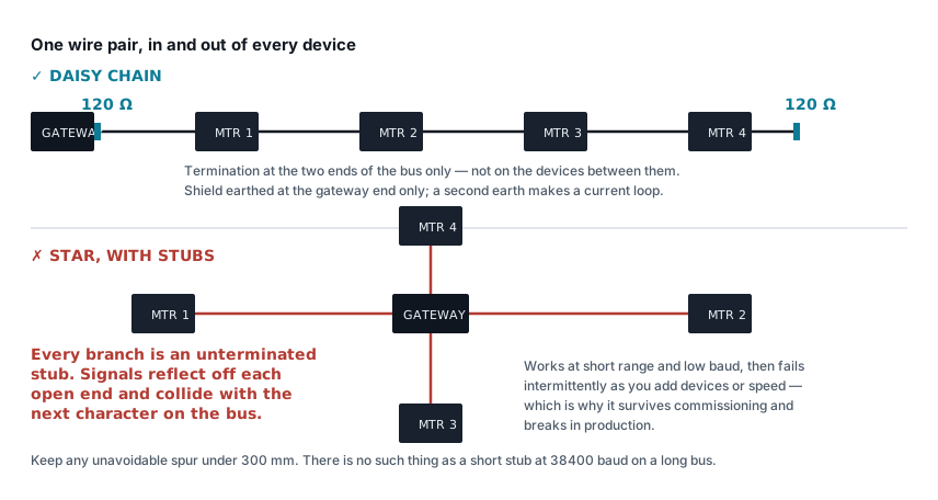
The cable must enter each device and leave it, forming one continuous line from one end of the bus to the other. No branches, no spurs, no home runs back to a central point.
Every branch is an unterminated stub. The signal travels down it, hits the open end, reflects, comes back and collides with whatever the bus is carrying by then. At low baud rates over short distances the reflections settle before they matter. Raise the baud rate, extend the cable or add devices and they stop settling in time.
If a spur is genuinely unavoidable, keep it under 300 mm. A star topology with 20 m legs is not a Modbus network; it is an intermittent fault with a schedule.
Termination: 120 Ω, at both ends, only at the ends
The cable has a characteristic impedance around 120 Ω. Terminating both physical ends with a matching 120 Ω resistor absorbs the signal rather than reflecting it.
Two rules that get broken constantly:
- Both ends, and only the ends. Not the electrical middle, not every device.
- Devices with built-in termination jumpers must have them switched off except on the two end devices. Every extra 120 Ω is another parallel load; five terminated devices present 24 Ω, the drivers cannot pull that hard, and the signal amplitude collapses.
The commonest field mistake is a bus where an installer enabled every termination jumper "to be safe". Measure resistance across A and B with the bus powered down: two terminations in parallel should read about 60 Ω. If it reads 30 Ω, someone has been thorough.
Short buses — under about 100 m at 9600 baud — often work with no termination at all. That is not a reason to omit it, because the same bus at 19200 with three more meters will not.
Fail-safe biasing
When no device is transmitting, the bus is idle and floating. Noise can then be interpreted as the start of a character, producing framing errors and phantom traffic.
Bias resistors — a pull-up on A and a pull-down on B — hold the idle state at a defined level. Most gateways and USB converters have them built in; some need a jumper. Bias at one point on the bus only, normally the master. Multiple biasing points fight each other and reduce the differential swing available for real data.
If the bus shows occasional errors when it is otherwise quiet, biasing is the first thing to check.
The third wire everybody omits
RS485 is a two-wire signalling system, not a two-wire system. The transceivers have a common-mode input range, typically −7 V to +12 V relative to their own ground. Both ends must sit within that window of each other.
Two meters on the same panel always do. A meter in a building 200 m away, fed from a different distribution board, may not — the difference in earth potential between two buildings can be several volts normally and much more during a fault.
So run three conductors: A, B and a signal common, connected to the COM or GND terminal on each device. It costs nothing at installation and it eliminates a class of fault that is nearly impossible to diagnose later.
Where the buildings are genuinely separate, or the run leaves a building, use galvanically isolated transceivers or an isolated repeater. Between separate structures with their own earth systems, fibre is the right answer — for the same potential-difference reason that separate earths destroy equipment.
Shield, earthed once
Use a twisted pair with an overall shield. Twisting is what makes the interference common-mode; the shield handles what is left.
Earth the shield at one end only, normally the gateway. Earthing both ends creates a loop between two points at slightly different potentials, and the resulting circulating current in the shield is exactly the noise the shield was fitted to stop.
The shield must be carried through every device as a continuous conductor, insulated from earth at each one, so that its single earth connection is the only one.
Cable and routing
- Twisted pair, 24 AWG or thicker, ~120 Ω characteristic impedance. Cable sold as "RS485 cable" or "Belden 3106A equivalent" is right. Cat5e works over short runs but is 100 Ω, and it is unshielded unless you bought STP.
- A and B must be the two conductors of the same pair. Using one wire from each of two different pairs destroys the twisting that makes the whole thing work. This is a common and completely invisible mistake.
- Separate from power cabling by at least 300 mm, and cross at 90° where they must meet. Never share a trunking compartment with motor or VFD cables.
- Never run RS485 in the same multicore as switched loads. A contactor coil sharing a cable with the bus injects a spike into it every operation.
- Surge protection where the bus leaves a building, on both data lines.
Length, baud and device count
| Baud | Practical maximum length |
|---|---|
| 9600 | 1,200 m |
| 19200 | 1,200 m |
| 38400 | 700 m |
| 115200 | 200 m |
Standard transceivers present one unit load each, and the specification allows 32 per segment. Many modern devices are quarter or eighth unit load, allowing 128 or more — check the datasheet rather than assuming either number. Beyond the limit, use a repeater, which also gives you a fresh segment with its own termination.
Choose the lowest baud rate that meets your polling interval. There is no prize for 115200. Reading twenty meters once a minute needs very little bandwidth, and 9600 baud is dramatically more robust over a long, noisy run.
Diagnosing a bus that misbehaves
In order, because each step is cheaper than the next:
- Power everything down and measure A to B. ~60 Ω means two terminations, correct. ~120 Ω means one. ~30 Ω or less means too many.
- Power up, no traffic, measure A to B. A biased idle bus reads a few hundred millivolts positive. Zero means no biasing.
- Check A/B polarity at every device. Reversed at one device kills that device only; reversed at the master kills everything. Labelling is inconsistent between vendors — A/B, D+/D−, and TX+/TX− do not always mean the same thing, so be prepared to swap.
- Disconnect half the bus. If the remaining half works, the problem is in the removed half — repeat by halving. This finds bad stubs and bad devices faster than anything else.
- Drop the baud rate. If errors disappear at 9600 that had been present at 38400, the problem is physical: reflections, stubs or length.
- Check for duplicate unit IDs. Two devices answering at once produces corrupt frames that look exactly like noise. A meter that resets its address on power failure can create this weeks after commissioning.
Only once the bus is clean is it worth looking at the protocol layer — register offsets, byte order and polling intervals are covered in Modbus RTU on energy meters, and the byte order question is settled in seconds with the float decoder.
Related articles
More on metering & iot.
 Metering & IoT
PROFIBUS and PROFINET: how each is wired, and what breaks
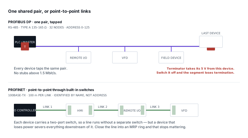
Purple cable at 150 Ω against green Ethernet, powered termination against none, device addresses against device names — and the fault each design invites.
8 min read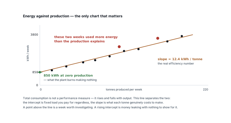 Metering & IoT
Turning meter data into savings: baselines, KPIs and alerts
Why total kWh is a useless measure, how to build an energy baseline against production, and the four analyses that actually find money in metering data.
6 min read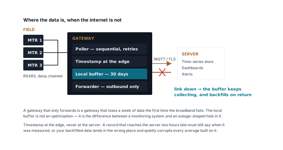 Metering & IoT
Building a Modbus energy monitoring gateway that stays up
Polling design, store-and-forward, timestamping at the edge, SD card wear and the naming convention you cannot change later — a field-grade gateway.
7 min read Metering & IoT
MQTT, Modbus TCP or HTTP: moving meter data to a server
Poll versus publish, what each protocol costs in bandwidth and firewall holes, how to design topics and payloads, and where each one genuinely belongs.
7 min read
Comments
Loading…