
Sizing a distribution transformer: kVA, %Z and fault level
Size a distribution transformer from maximum demand, not connected load — and why the per cent impedance on the nameplate is what decides your switchgear.
A transformer is the one item on an LT project you cannot quietly correct later. Cable can be pulled again, a breaker can be swapped in an afternoon, a panel can be extended. A 315 kVA transformer sitting on its plinth with the HV terminated is there for the next thirty years, and everything downstream — the incomer, the busbar, every breaker in the panel — was chosen to match two numbers on its nameplate.
Those two numbers are the rating in kVA and the impedance in per cent. Most transformer sizing calculations only take the first seriously. This walks through both, with a worked example, and the arithmetic is all in the transformer sizing calculator if you would rather put your own figures in.
Start with maximum demand, not connected load
The most common sizing error happens before any transformer arithmetic starts: adding up every nameplate on site and calling that the load.
Connected load is what would be drawn if everything ran flat out at the same instant. That never happens. The standby pump does not run with the duty pump. The welding set is on for four minutes in an hour. Half the lighting is off in daylight. What the transformer must supply is maximum demand — connected load multiplied by a demand factor for each category:
| Load category | Connected | Demand factor | Demand |
|---|---|---|---|
| Process motors | 210 kW | 0.65 | 136.5 kW |
| Lighting and fans | 25 kW | 0.90 | 22.5 kW |
| Welding and utility | 40 kW | 0.50 | 20.0 kW |
| Office and AC | 30 kW | 0.80 | 24.0 kW |
| Total | 305 kW | 203 kW |
Two thirds of the connected load. Size on 305 kW and you buy a transformer 50 % larger than the plant will ever ask for, then pay for that decision every hour it is energised.
The demand factors above are typical starting points, not standards. If the plant exists, do not guess at all — clamp the incomer or read the existing meter's maximum demand register over a month. A DISCOM bill showing recorded MD is better data than any table in any book, including this one. Guess only for a greenfield site, and guess conservatively for process loads that run continuously.
Why the rating is in kVA and not kW
A transformer does not care what your load does with the current. It cares about the current itself, because that is what heats the windings. So it is rated in apparent power:
kVA = kW / power factor
At 203 kW and a power factor of 0.80, the transformer must supply 254 kVA. Fix the power factor to 0.95 and the same 203 kW of real work needs only 214 kVA — 40 kVA of capacity released without adding a single kW of useful load.
Add a sensible future margin of 15 % and watch what that does to the purchase:
| Power factor | Demand | With 15 % margin | Transformer |
|---|---|---|---|
| 0.80 | 254 kVA | 292 kVA | 315 kVA |
| 0.95 | 214 kVA | 246 kVA | 250 kVA |
An APFC panel on the LT side moves you down a full standard frame — a smaller transformer, a smaller HT breaker, a smaller LT incomer, and lower losses forever after. It is one of the few decisions in electrical design that is cheaper and better, which is why it should be made before the transformer is ordered rather than two years into the DISCOM penalties.
How much spare capacity is right
Transformers come in standard ratings under IS 1180 — 25, 63, 100, 160, 200, 250, 315, 400, 500, 630, 1000 kVA and upward — so you are always rounding up to one of those. The question is how far up.
| Loading | Verdict |
|---|---|
| Under 50 % | Oversized. You are paying no-load loss around the clock for capacity nobody uses. |
| 50–60 % | Comfortable, arguably generous. Reasonable if a known expansion is funded. |
| 60–80 % | The target. Near peak efficiency, with room to grow into. |
| 80–100 % | Working hard. Start the paperwork for the next one. |
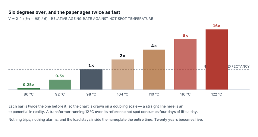
| Over 100 % | Insulation life roughly halves for every 6 °C of extra winding temperature. Short peaks are fine; a permanent overload is a slow write-off. |
Transformer efficiency peaks where load loss equals no-load loss, which for most distribution units lands between 40 % and 60 % loading. Efficiency is not the only consideration though — a transformer loaded at 45 % is efficient and expensive, because you bought copper and core you are not using.
The second number: per cent impedance
Every nameplate carries an impedance figure — 4.5 %, 5 %, 6.25 %. It is the fraction of rated primary voltage you must apply, with the secondary short-circuited, to drive full load current through the windings. It is a measure of how much the transformer resists a fault.
That definition is more useful turned inside out:
Fault current = Full load current / (Z% / 100)
At 5 % impedance, a transformer will deliver twenty times its full load current into a bolted fault on its terminals. At 4.5 %, twenty-two times.
This is why impedance is not something to minimise. Low impedance gives better voltage regulation — the terminal voltage sags less as load comes on — and a higher fault level. High impedance gives the opposite. IS 1180 fixes the value by rating so that switchgear selection stays predictable across manufacturers, and a transformer quoted at an unusually low impedance is not a bargain; it is a higher fault level you now have to buy switchgear for.
Working the fault level
Take the 315 kVA transformer chosen above, 11 kV / 433 V, 5 % impedance.
LV full load current = 315,000 / (1.732 × 433) = 420 A
HV full load current = 315,000 / (1.732 × 11,000) = 16.5 A

Terminal fault current = 420 / 0.05 = 8.4 kA rms
Peak asymmetrical      = 8.4 × 2.5 = 21 kA
Fault level            = 315 / 0.05 = 6.3 MVA
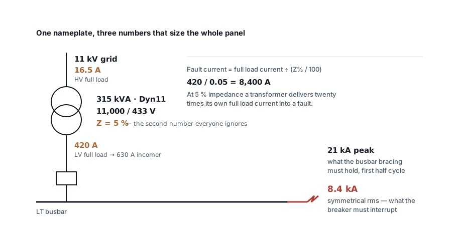
Three things fall out of those four lines.
The incomer. 420 A of full load current means a 630 A frame — not a 400 A one, which would be running at its limit from day one with no allowance for the sustained overloads a transformer tolerates.
The breaking capacity. Every device on that busbar must interrupt 8.4 kA. The nearest standard rating is 10 kA, and this is exactly where people save money they later spend twice. If there is any prospect of the transformer being uprated to 500 kVA — a very ordinary thing to happen five years in — the fault level goes to 13.3 kA and every 10 kA device in the panel becomes non-compliant. Specify 25 kA and the panel survives the upgrade.
The bracing. The 21 kA peak is a mechanical figure, not an electrical one. It is what the busbar supports must hold during the first half cycle, and it is the reason busbar support spacing tightens as fault level rises. Breaking capacity and short-time withstand are two different ratings answering two different failure modes; a device can have plenty of one and not enough of the other.
Two assumptions are baked into the arithmetic above. It ignores the impedance of the 11 kV network behind the transformer, which in reality only ever lowers the fault current — so the figure is conservative, which is the right direction to be wrong in. And it ignores motor contribution: running motors briefly feed a fault as they spin down, adding roughly four times their combined full load current for the first few cycles. On a motor-heavy plant, add it in.
Note also that this is the fault current at the terminals. A few metres of cable drops it sharply, which is why the terminal figure is the wrong number to use when checking discrimination at a downstream board.
What oversizing actually costs
A transformer has two losses. No-load loss is the core magnetising the steel; it is there from the moment the HV is charged and it does not care whether the plant is running. Load loss is I²R in the windings and rises with the square of loading.
For a 315 kVA unit, typical figures are around 550 W no-load and 3.2 kW load loss at full load. Run that out over a year at 76 % loading, a plant working 4,000 hours, and ₹8 per unit:
No-load: 0.55 kW × 8,760 h            = 4,818 kWh  ≈ ₹38,500
Load:    3.2 kW × 0.76² × 4,000 h     = 7,393 kWh  ≈ ₹59,100
                                                     ─────────
                                                     ₹97,600 / year
Nearly ₹40,000 of that is spent whether the factory produces anything or not. Step up one frame to 400 kVA for comfort and the no-load loss rises with it — call it another ₹8,000 a year, every year, for the life of the installation. That is a real number to weigh against the flexibility the larger unit buys.
It is also the argument for a star-rated transformer. The premium on an energy efficient unit is recovered from no-load loss alone, and it is recovered whether or not the plant is busy.
The rest of the nameplate
The two numbers this article is about are not the only ones that matter when the transformer arrives:
| Field | Why it matters |
|---|---|
| Voltage ratio | Usually 11,000 / 433 V. The 433 V is a no-load figure — it sags towards 415 V under load, which is why you size the incomer on 433 V |
| Vector group | Dyn11 for most distribution duty. The delta HV winding traps triplen harmonics; the neutral makes single-phase loads possible |
| Impedance | The fault level, as above |
| No-load / load loss | The operating cost, as above |
| Temperature rise | Typically 45 °C oil / 50 °C winding. It sets what ambient the ratings assume |
| Tap range | ±5 % in 2.5 % steps is standard. Off-load tap changers must only be moved with the transformer de-energised |
That last one causes more site incidents than it should.
Before you release the order
- Size on maximum demand, measured if the plant exists.
- Correct power factor before choosing the rating, not after.
- Aim to land at 60–80 % loading on day one.
- Take the fault level from impedance, and specify switchgear for the transformer you might have in ten years, not the one arriving this month.
- Check the cable to the panel against the derated LV full load current, not the connected load.
- If a DG set backs the same board, size it separately — motor starting usually governs there, and it will not give the same answer.
Put your own figures into the transformer sizing calculator and it will return full load current on both windings, the loading percentage, terminal fault current, peak asymmetrical current and the standard breaker frame and breaking capacity to match.
One caution worth repeating: the fault figures here assume an infinite source and healthy nameplate data. For anything being submitted for approval, get the DISCOM's declared fault level at the point of supply and use that. A calculation tells you what to expect; the utility tells you what you actually have.
Standards referenced
- IS 1180 — Outdoor Type Oil Immersed Distribution Transformers up to and including 2500 kVA, 33 kV — Specification. Bureau of Indian Standards
Titles are given as commonly published. Check the current edition with the publisher before relying on a clause in professional work.
Related articles
More on supply, demand & generation.
 Supply, demand & generation
Why distribution transformers fail: one mechanism, ten routes to it
Almost every failure mode ends as heat or water in the paper. The 6 °C rule that quantifies it, and the oil tests that see it coming months ahead.
8 min read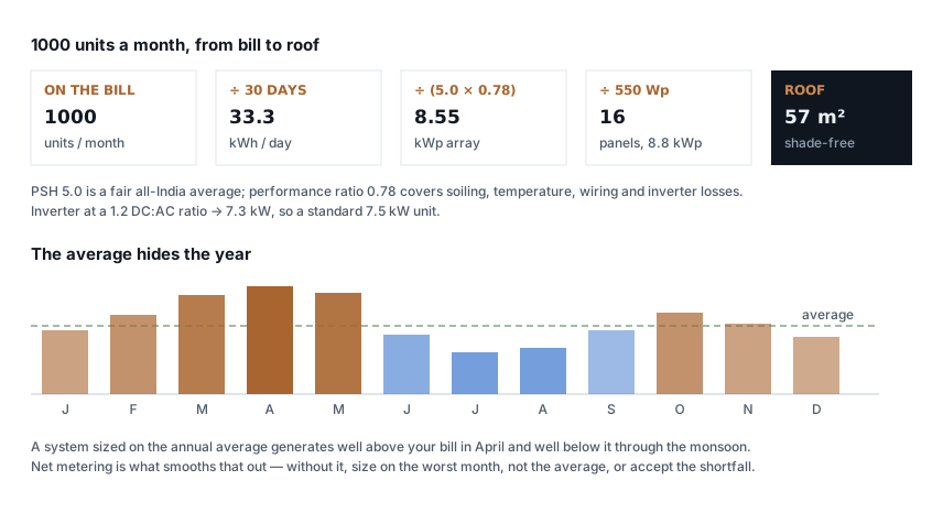 Supply, demand & generation
How many solar panels for 1000 units a month?
The arithmetic from your bill to a panel count and a roof area, why the annual average misleads, and the four things that decide whether you actually get it.
6 min read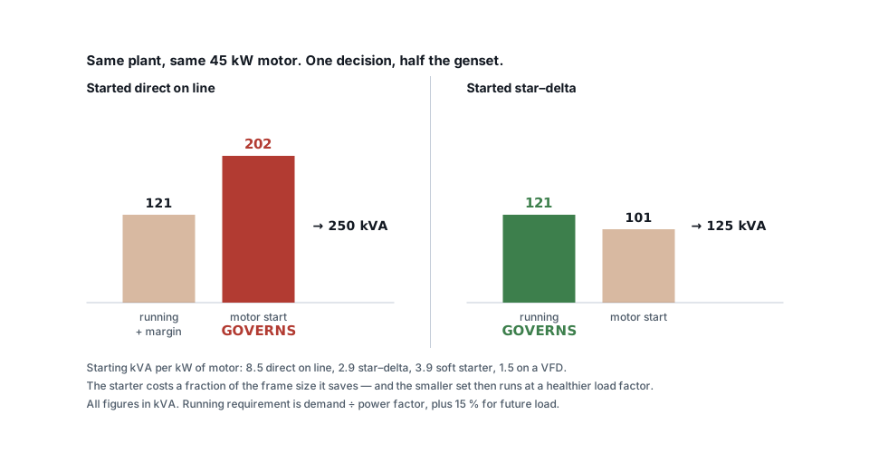 Supply, demand & generation
DG set sizing: why motor starting usually governs
Two calculations decide a generator rating and most quotations do only one. A worked example where the starter choice halves the frame size.
7 min read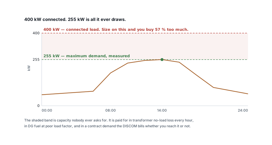 Supply, demand & generation
Connected load, maximum demand and diversity factor
The three numbers get used as though they were one. Which to size on, typical demand factors by load type, and what getting it wrong costs on the bill.
7 min read
Comments
Loading…